week2
introduction
This week we will cover the basic progress of embedded programming using arduino.
basic information
Arduino is an open-source hardware and software platform based on microcontrollers and development boards. In this section the typical type of board we'll use is the Seeed Studio XIAO ESP32C3 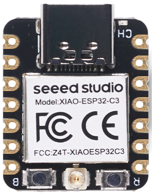 Seeed Studio XIAO ESP32C3 is an IoT mini development board based on the Espressif ESP32-C3 WiFi/Bluetooth dual-mode chip, featuring a 32-bit RISC-V CPU that delivers powerful computing performance with its efficient architecture. It has excellent radio frequency performance, supporting IEEE 802.11 b/g/n WiFi, and Bluetooth 5 (BLE) protocols. This board comes included with an external antenna to increase the signal strength for your wireless applications. It also has a small and exquisite form-factor combined with a single-sided surface-mountable design. It is equipped with rich interfaces and has 11 digital I/O that can be used as PWM pins and 3 analog I/O that can be used as ADC pins. It supports four serial interfaces such as UART, I2C and SPI. There is also a small reset button and a bootloader mode button on the board. XIAO ESP32C3 is fully compatible with the Grove Shield for Seeeduino XIAO and Seeeduino XIAO Expansion board except for the Seeeduino XIAO Expansion board, the SWD spring contacts on the board will not be compatible. With regard to the features highlighted above, XIAO ESP32C3 is positioned as a high-performance, low-power, cost-effective IoT mini development board, suitable for low-power IoT applications and wireless wearable applications.
-features This is the basic layout 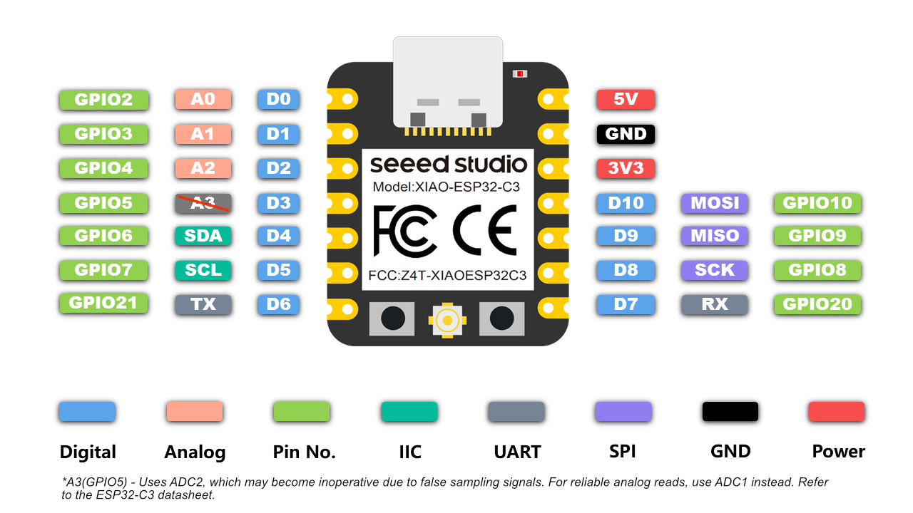
steps
Now we're going to learn how to do embedded programming using arduino. Here are the steps:
Requirements
To follow this tutorial, you’ll need:
- An Arduino board (e.g., Seeed Studio XIAO ESP32C3)
- A USB cable (usually Type-A to Type-B)
- A computer with the Arduino IDE installed
- An LED and sensors, we use an EMG sensor in this example
- A breadboard and jumper wires (optional for external LED)
Setting Up the Arduino IDE
- Download the IDE: Visit arduino.cc and download the Arduino IDE for your operating system.
- Install the IDE: Follow the installation instructions for your OS.
- Connect Your Arduino: Plug your Arduino into your computer via the USB cable.
- Select Your Board: Open the IDE, go to
Tools > Board, and select your Arduino model (e.g., Seeed Studio XIAO ESP32C3). - Select the Port: Go to
Tools > Portand choose the port your Arduino is connected
basic layout: 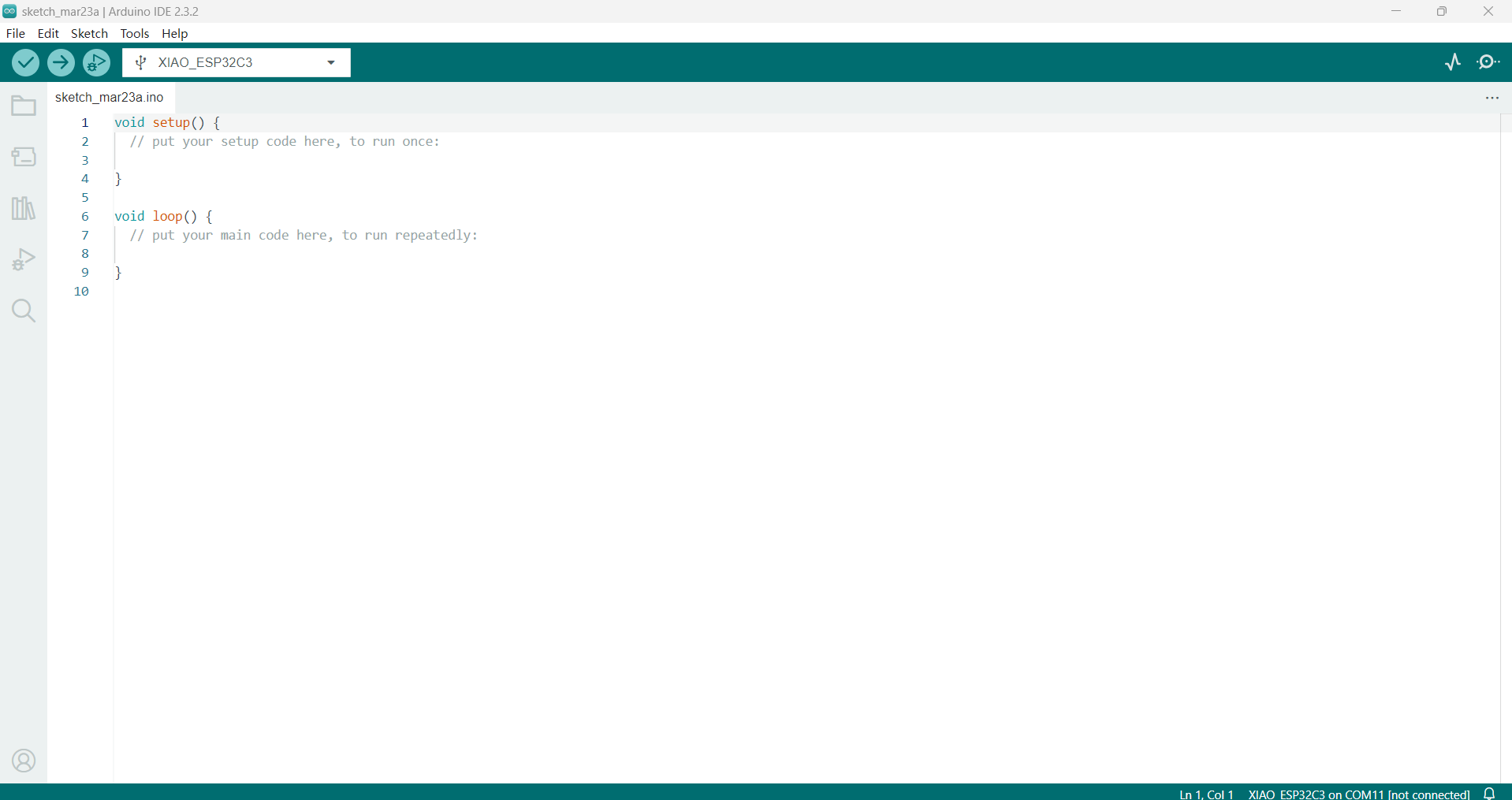
now start sketching:
#define BAUD_RATE 115200       // 串口波特率
#define INPUT_PIN A0           // 信号输入
#define DETECT_PIN 2           // 检测输入
#define Vref (1.65 / 5 * 1024) // 抬升电压

// 窗口
#define BUFFER_SIZE 128           // 窗口大小
int circular_buffer[BUFFER_SIZE]; // 环形数组
int data_index, sum;              // 数据索引

void setup() {
Serial.begin(BAUD_RATE);
pinMode(DETECT_PIN, INPUT); // 设置DETECT_PIN为输入模式
}

void loop() {
// 计算经过的时间
static unsigned long past = 0;
unsigned long present = micros();
unsigned long interval = present - past;
past = present;

static long timer = 0;
timer -= interval;

static bool ledoffFlag = 1;

if (timer < 0) {
  timer += 1000000 / SAMPLE_RATE;
  int sensor_value = analogRead(INPUT_PIN);
  int detect_value = digitalRead(DETECT_PIN); // 读取DETECT_PIN的数字信号
  int signal = Filter(sensor_value);
  int emgRaw = signal - Vref;

  if (detect_value == HIGH) {
    Serial.println(String(emgRaw) + "," + String(signal) + ",1");

  } else {
    Serial.println(String(emgRaw) + ",0,0");
  }
}
}

/****************************滤波************************************/

// >>> Butterworth IIR Digital Filter: bandpass
// 	Sampling Rate:500.0 Hz ,Frequency:[70.0, 110.0] Hz
// 	Order: 4.0 ,implemented as second-order sections (biquads)
float Filter(float input) {
float output = input;
{
  static float z1, z2; // filter section state
  float x = output - (-0.55195385 * z1) - (0.60461714 * z2);
  output = 0.00223489 * x + (0.00446978 * z1) + (0.00223489 * z2);
  z2 = z1;
  z1 = x;
}

{
  static float z1, z2; // filter section state
  float x = output - (-0.86036562 * z1) - (0.63511954 * z2);
  output = 1.00000000 * x + (2.00000000 * z1) + (1.00000000 * z2);
  z2 = z1;
  z1 = x;
}

{
  static float z1, z2; // filter section state
  float x = output - (-0.37367240 * z1) - (0.81248708 * z2);
  output = 1.00000000 * x + (-2.00000000 * z1) + (1.00000000 * z2);
  z2 = z1;
  z1 = x;
}

{
  static float z1, z2; // filter section state
  float x = output - (-1.15601175 * z1) - (0.84761589 * z2);
  output = 1.00000000 * x + (-2.00000000 * z1) + (1.00000000 * z2);
  z2 = z1;
  z1 = x;
}

return output;
}
this is a string of code that will read the EMG signal from the sensor, filter it, and output it to the serial port. The code also includes a timer to send data at a fixed rate.
now let's add a LED to the circuit and use it to indicate when the EMG signal is above a certain threshold. (I used AI to support me for this section, my prompt is to use the EMG signal to control the LED, copy and paste the code above and ask it modifiy it into a LED control program, using D9 for the LED pin and A0 for the EMG signal input pin)
#define BAUD_RATE 115200       // 串口波特率
#define INPUT_PIN A0          // 信号输入
#define DETECT_PIN 2          // 检测输入
#define LED_PIN D9            // LED输出引脚(使用D9)
#define Vref (1.65 / 5 * 1024) // 抬升电压
#define THRESHOLD 500         // EMG信号阈值(可调整)

// 窗口
#define BUFFER_SIZE 128           // 窗口大小
int circular_buffer[BUFFER_SIZE]; // 环形数组
int data_index, sum;             // 数据索引

void setup() {
  Serial.begin(BAUD_RATE);
  pinMode(DETECT_PIN, INPUT);    // 设置DETECT_PIN为输入模式
  pinMode(LED_PIN, OUTPUT);      // 设置LED_PIN为输出模式
  digitalWrite(LED_PIN, LOW);    // 初始关闭LED
}

void loop() {
  // 计算经过的时间
  static unsigned long past = 0;
  unsigned long present = micros();
  unsigned long interval = present - past;
  past = present;

  static long timer = 0;
  timer -= interval;

  if (timer < 0) {
    timer += 1000000 / SAMPLE_RATE;
    int sensor_value = analogRead(INPUT_PIN);
    int detect_value = digitalRead(DETECT_PIN);
    int signal = Filter(sensor_value);
    int emgRaw = signal - Vref;

    // 根据EMG信号幅度控制LED
    if (abs(emgRaw) > THRESHOLD) {
      digitalWrite(LED_PIN, HIGH);  // EMG信号超过阈值时点亮LED
    } else {
      digitalWrite(LED_PIN, LOW);   // 低于阈值时关闭LED
    }

    // 串口输出保持不变
    if (detect_value == HIGH) {
      Serial.println(String(emgRaw) + "," + String(signal) + ",1");
    } else {
      Serial.println(String(emgRaw) + ",0,0");
    }
  }
}

/****************************滤波************************************/
// Butterworth IIR Digital Filter: bandpass
float Filter(float input) {
  float output = input;
  {
    static float z1, z2;
    float x = output - (-0.55195385 * z1) - (0.60461714 * z2);
    output = 0.00223489 * x + (0.00446978 * z1) + (0.00223489 * z2);
    z2 = z1;
    z1 = x;
  }
  {
    static float z1, z2;
    float x = output - (-0.86036562 * z1) - (0.63511954 * z2);
    output = 1.00000000 * x + (2.00000000 * z1) + (1.00000000 * z2);
    z2 = z1;
    z1 = x;
  }
  {
    static float z1, z2;
    float x = output - (-0.37367240 * z1) - (0.81248708 * z2);
    output = 1.00000000 * x + (-2.00000000 * z1) + (1.00000000 * z2);
    z2 = z1;
    z1 = x;
  }
  {
    static float z1, z2;
    float x = output - (-1.15601175 * z1) - (0.84761589 * z2);
    output = 1.00000000 * x + (-2.00000000 * z1) + (1.00000000 * z2);
    z2 = z1;
    z1 = x;
  }
  return output;
}
This is the code for the program
now start connecting, it should work