week3
introduction
This week we will cover the basics of electronics design. We'll start from drawing a circuit board using software and manufacture them for later experiments.
What is Electronics Design?
Electronics design is the process of creating circuits to perform specific functions, such as powering devices, processing signals, or controlling systems. It involves selecting components, calculating values, and arranging them to work together efficiently and safely.
Tools and Materials
To get started, you’ll need:
- Breadboard: For prototyping without soldering.
- Multimeter: To measure voltage, current, and resistance.
- Components: Resistors, LEDs, capacitors, transistors, etc.
- Power Supply: A battery (e.g., 9V) or a bench power supply.
- Wires: Jumper wires or solid-core wire for connections.
- Design Software: Optional tools like KiCad, Eagle, or Fritzing for schematics.
- Soldering Kit: For permanent circuits (optional).
Basic Concepts
Before designing, understand these key ideas:
- Voltage (V): The electrical potential difference, measured in volts.
- Current (I): The flow of electrons, measured in amperes (amps).
- Resistance (R): Opposition to current flow, measured in ohms (Ω).
- Ohm’s Law:
V = I × R– relates voltage, current, and resistance. - Series vs. Parallel: Components can be connected end-to-end (series) or side-by-side (parallel), affecting total resistance and current flow.
In this practice we'll use LCEDA as an example to demonstrate the basic concepts of software aided electronics design, and use a circuit that controls two LED lights as an example. This is is a basic layout 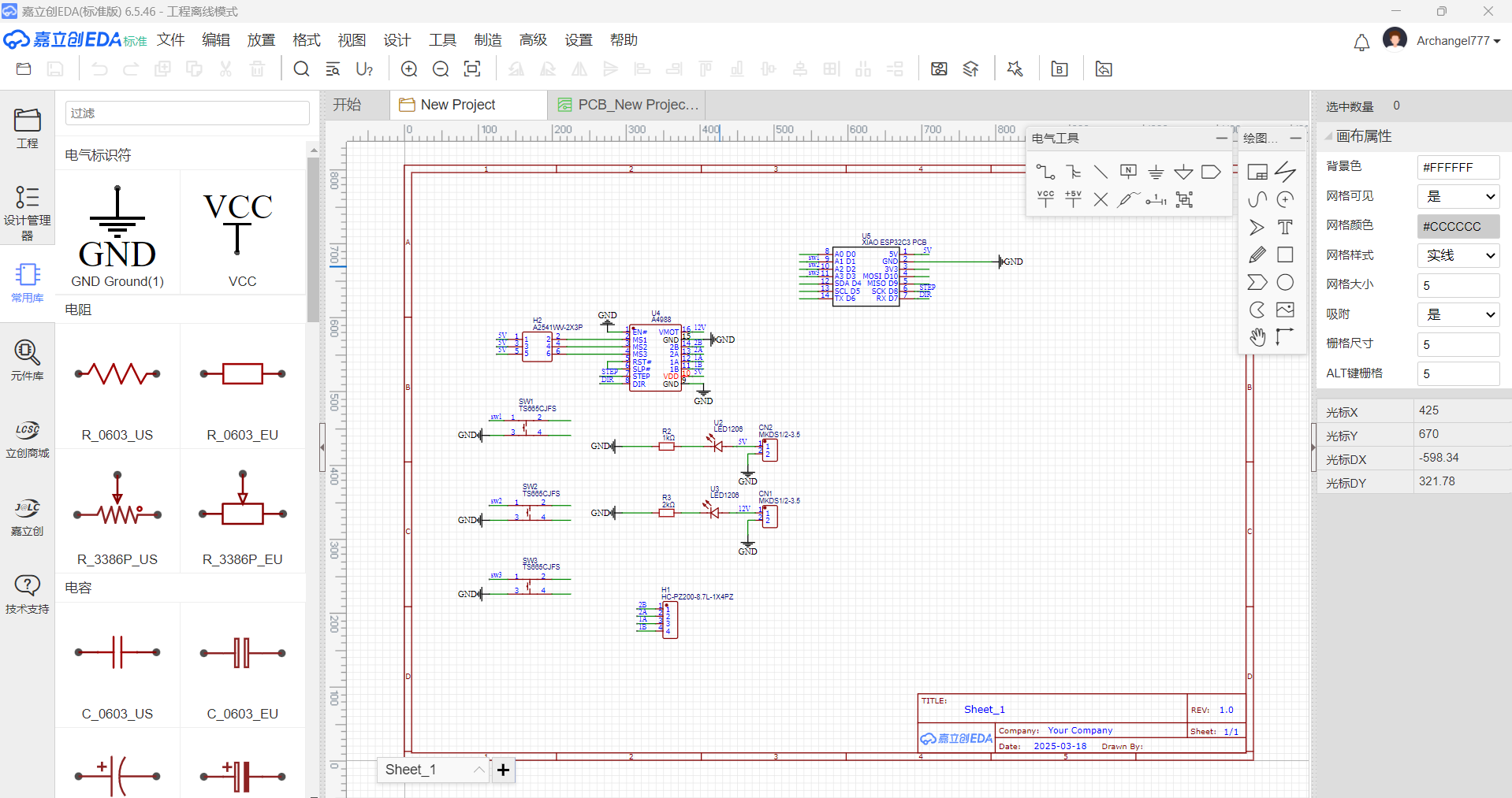
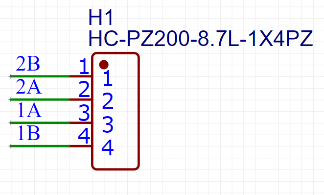
First, add the boards: 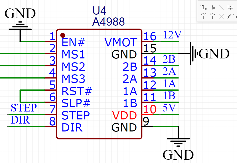
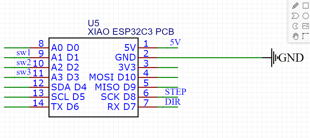 make sure to mark out the specific labels to note where these pins would be connected to the components.
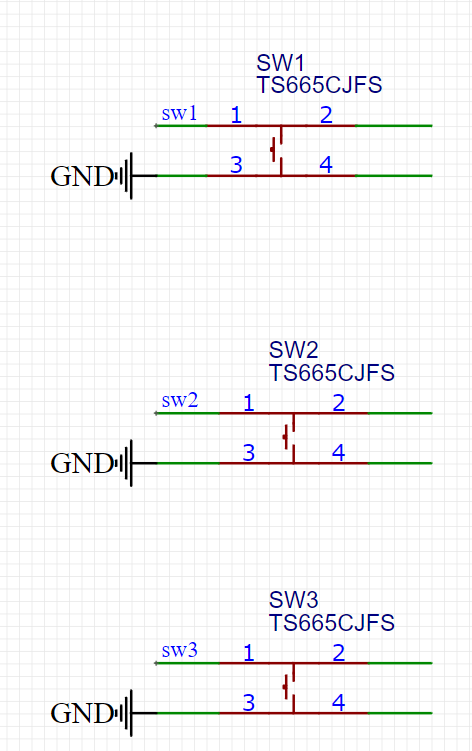
Next, add the components: 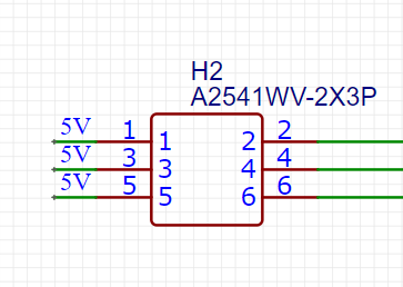
 and connect the LEDS and resistors
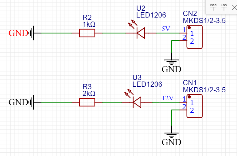
Connect all components, it should look like this: 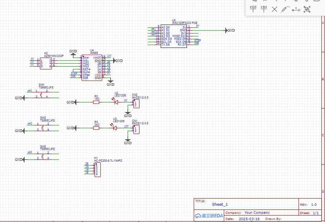
Now start viewing it in the PCB mode of the software: 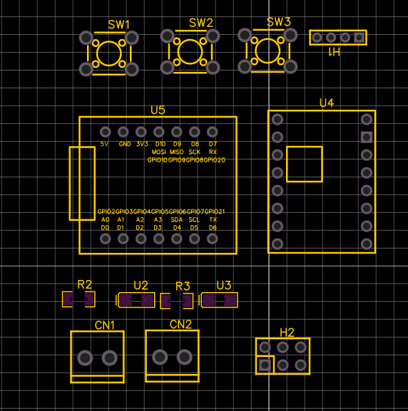 connect them according to the sketch, leave the ground pins
 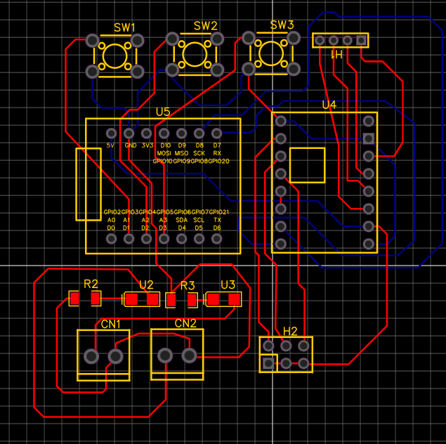 now connect the ground pins, it should be completed automatically
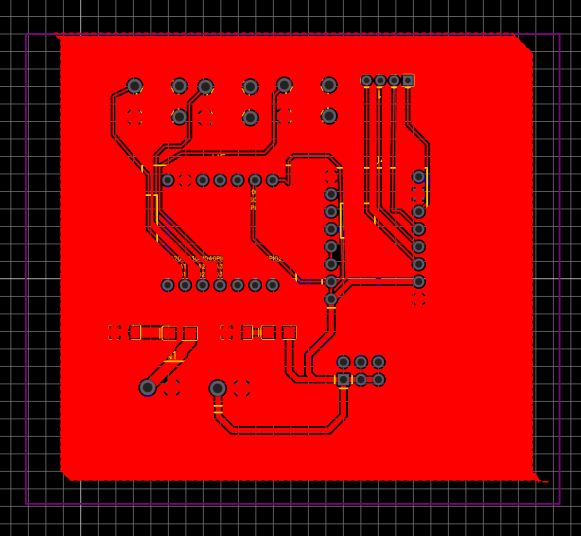
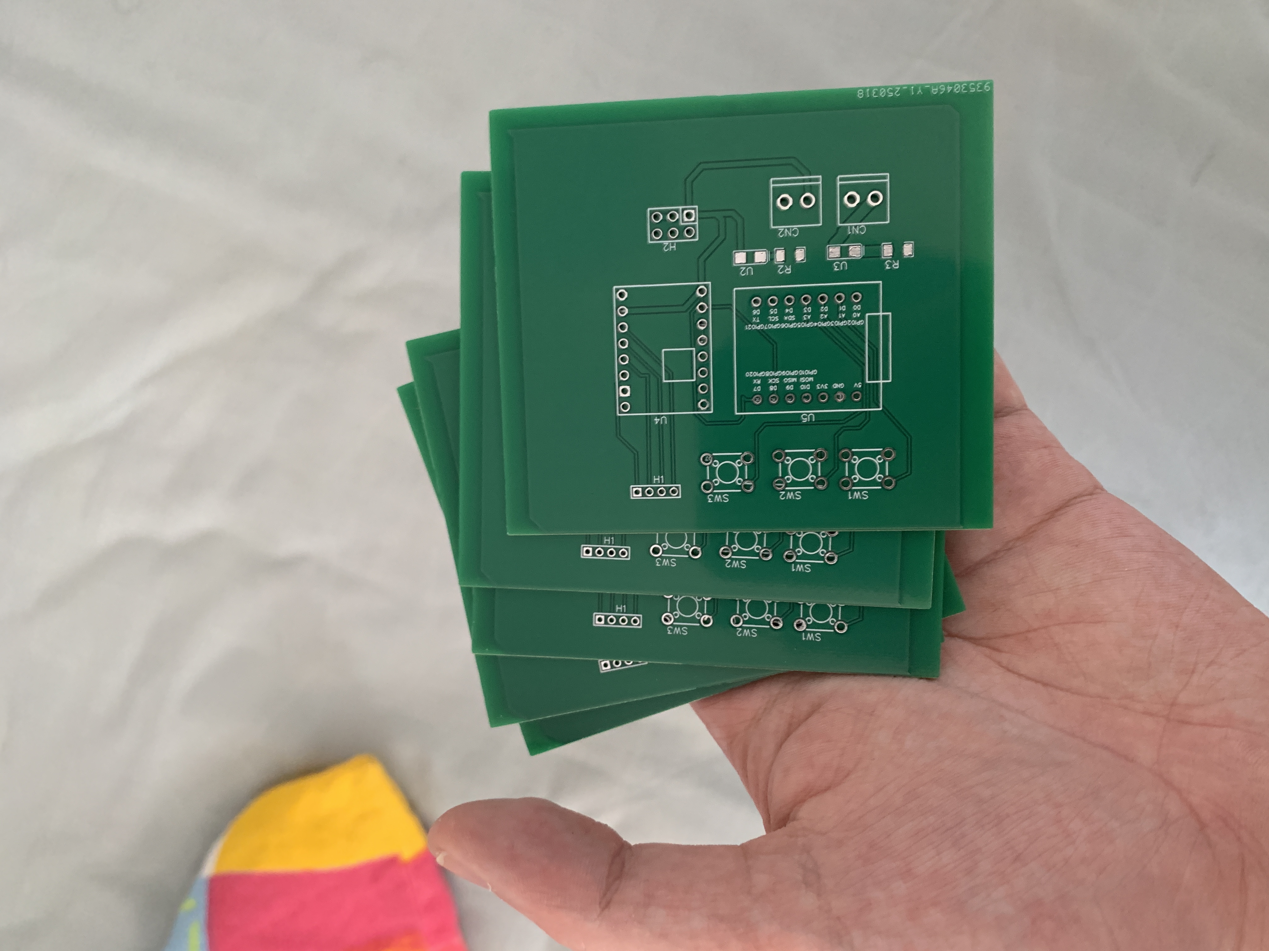
This software also allows you to send this PCB file to it's servers and they'll process and manufacture it for you. Now we can use it for further experiments