

Arduino application
1.Software
Yu can download Arduino IDE from www.arduino.cc according to your PC's version and then install by youself. 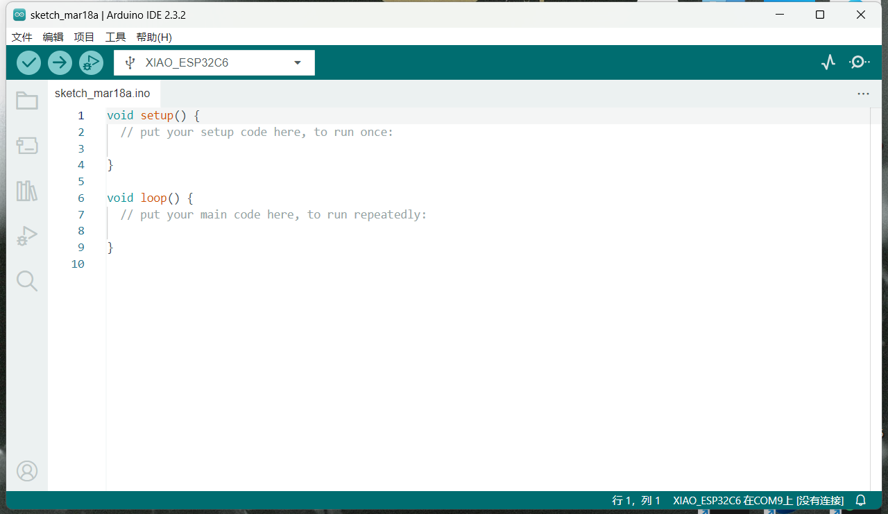
2.Hardware
Data from(https://wiki.seeedstudio.com/XIAO_ESP32C3_Getting_Started/)
Seeed Studio XIAO ESP32C3 is an IoT mini development board based on the Espressif ESP32-C3 WiFi/Bluetooth dual-mode chip, featuring a 32-bit RISC-V CPU that delivers powerful computing performance with its efficient architecture. 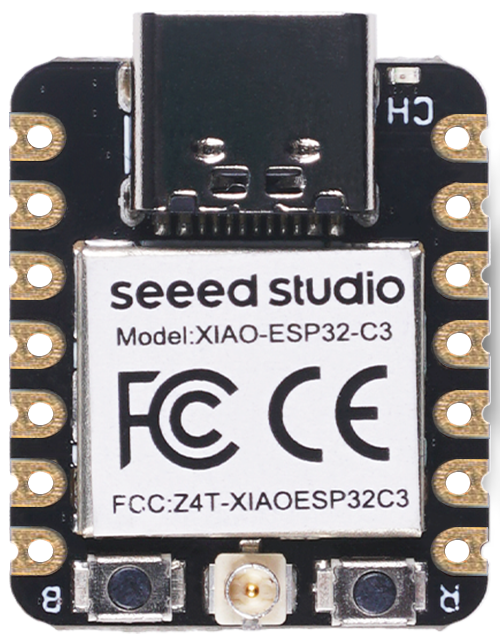
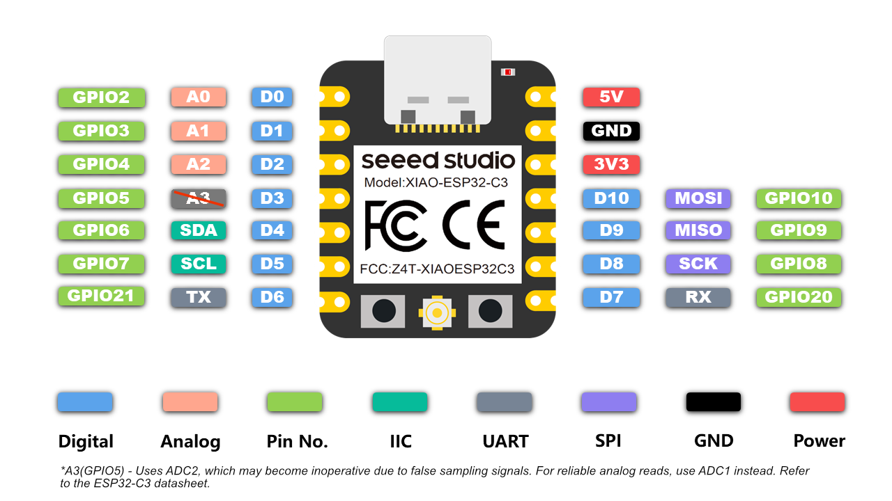
Pinout diagram
| Item | Seeed Studio XIAO ESP32C3 | Seeeduino XIAO | Seeed XIAO RP2040 | Seeed XIAO nRF52840 | Seeed XIAO nRF52840 Sense |
|---|---|---|---|---|---|
| Processor | ESP32-C3 32-bit RISC-V @160MHz | SAMD21 M0+@48MHz | RP2040 Dual-core M0+@133Mhz | nRF52840 M4F@64MHz | nRF52840 M4F@64MHz |
| Wireless Connectivity | WiFi and Bluetooth 5 (BLE) | N/A | N/A | Bluetooth 5.0/BLE/NFC | Bluetooth 5.0/BLE/NFC |
| Memory | 400KB SRAM, 4MB onboard Flash | 32KB SRAM 256KB FLASH | 264KB SRAM 2MB onboard Flash | 256KB RAM, 1MB Flash 2MB onboard Flash | 256KB RAM,1MB Flash 2MB onboard Flash |
| Built-in Sensors | N/A | N/A | N/A | N/A | 6 DOF IMU (LSM6DS3TR-C), PDM Microphone |
| Interfaces | I2C/UART/SPI | I2C/UART/SPI | I2C/UART/SPI | I2C/UART/SPI | I2C/UART/SPI |
| PWM/Analog Pins | 11/4 | 11/11 | 11/4 | 11/6 | 11/6 |
| Onboard Buttons | Reset/ Boot Button | N/A | Reset/ Boot Button | Reset Button | Reset Button |
| Onboard LEDs | Charge LED | N/A | Full-color RGB/ 3-in-one LED | 3-in-one LED/ Charge LED | 3-in-one LED/ Charge LED |
| Battery Charge Chip | Built-in | N/A | N/A | BQ25101 | BQ25101 |
| Programming Languages | Arduino/ MicroPython | Arduino/ CircuitPython | Arduino/ MicroPython | Arduino/ CircuitPython | Arduino/ CircuitPython |
3.Arduino Output
Project Definition
This Arduino project demonstrates basic digital output control using the Seeed Studio XIAO ESP32C3 development board. It creates a blinking LED effect through GPIO manipulation, serving as a fundamental example of hardware interaction in embedded systems. The project uses an external LED connected to pin D10 since the XIAO ESP32C3 lacks a built-in LED.
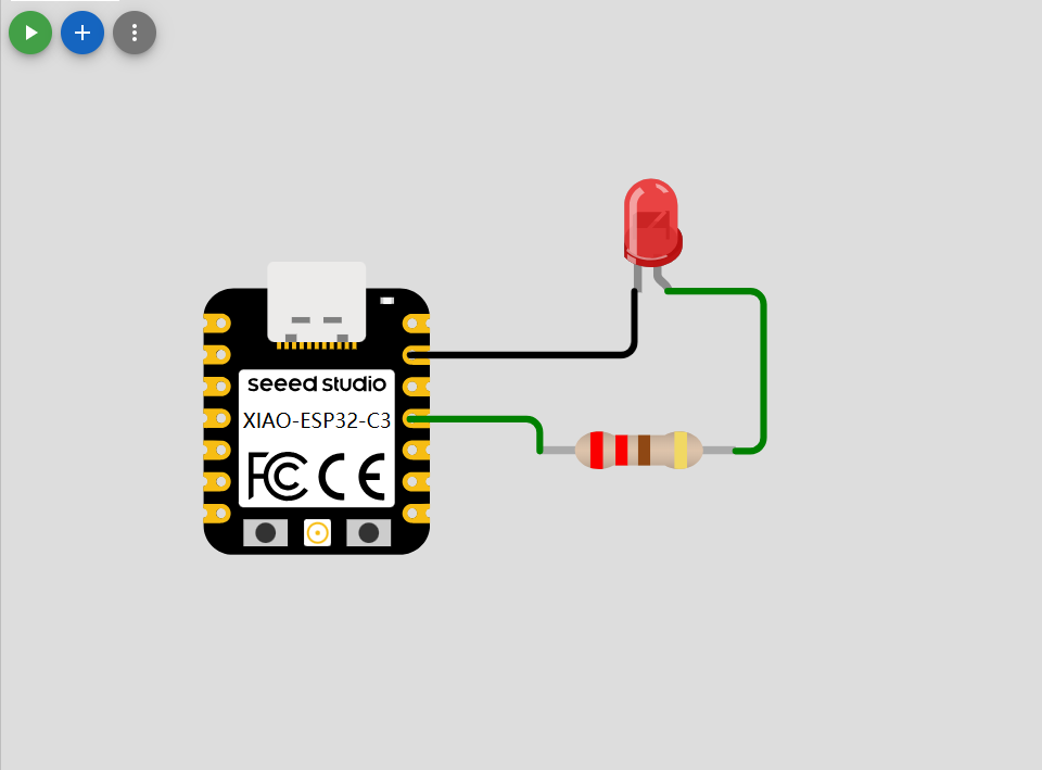
Wiring Diagram
- Connect LED cathode (shorter leg) to GND.
- Connect LED anode (longer leg) to D10 through a 220Ω current-limiting resistor
- Power the board via USB
Code Implementation
// define led according to pin diagram in article
const int led = D10; // there is no LED_BUILTIN available for the XIAO ESP32C3.

void setup() {
  // initialize digital pin led as an output
  pinMode(led, OUTPUT);
}

void loop() {
  digitalWrite(led, HIGH);   // turn the LED on
  delay(1000);               // wait for a second
  digitalWrite(led, LOW);    // turn the LED off
  delay(1000);               // wait for a second
}
Expected Effect
The LED will alternate between ON and OFF states at 1-second intervals. This demonstrates:
- Digital Output Control: GPIO pin voltage switching between 0V (LOW) and 3.3V (HIGH)
- Timing Functions: Using delay() for temporal control
- Circuit Protection: Proper current limitation through resistor
4.Arduino Input
Project Definition
This Arduino project implements an intelligent distance monitoring system using an HC-SR04 ultrasonic sensor and LED indicator. It continuously measures environmental distances and activates an LED (connected to D10) when objects exceed 200cm, demonstrating:
- Real-time distance measurement (0-400cm range)
- Threshold-based output control
- Serial data monitoring (count & distance values)
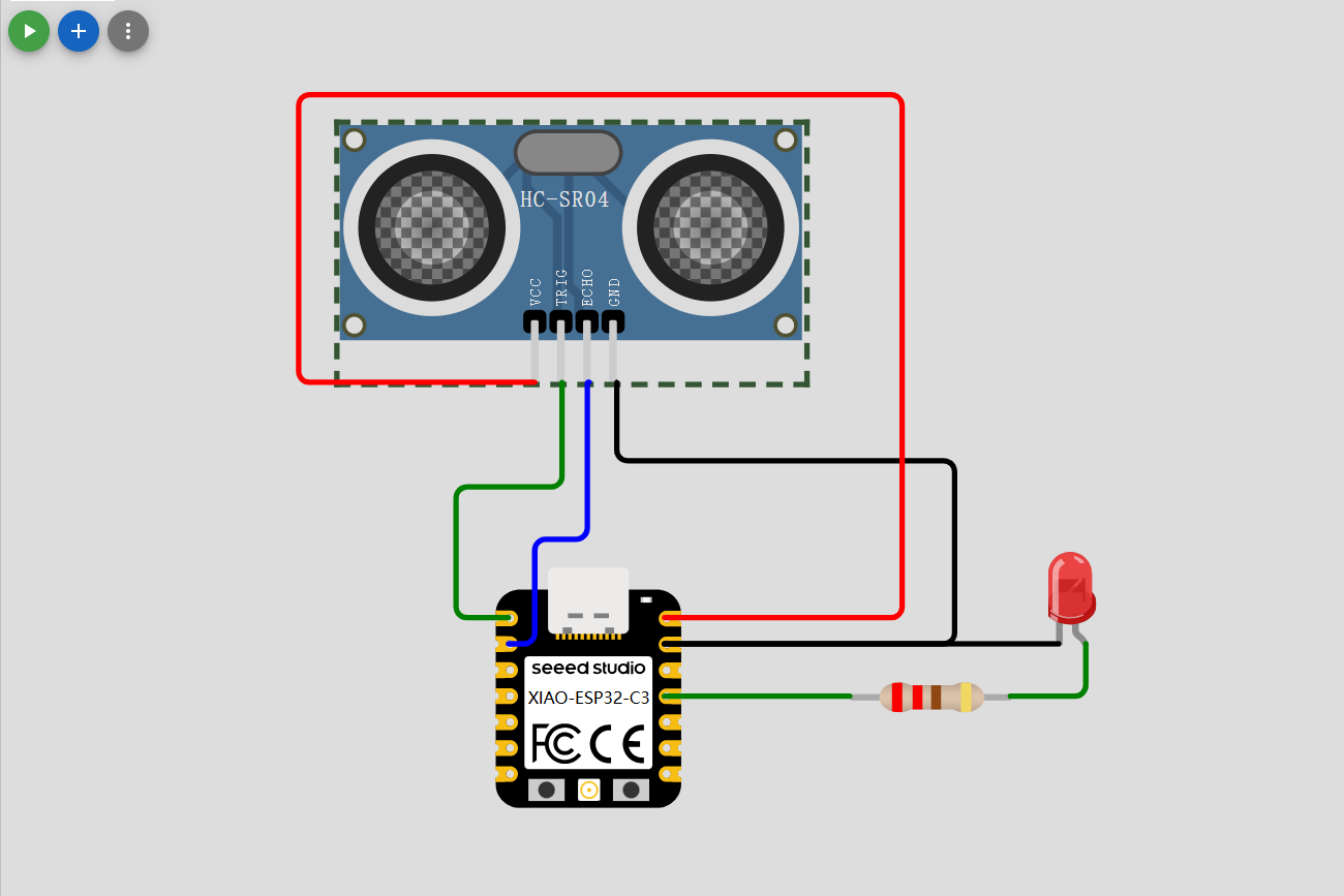
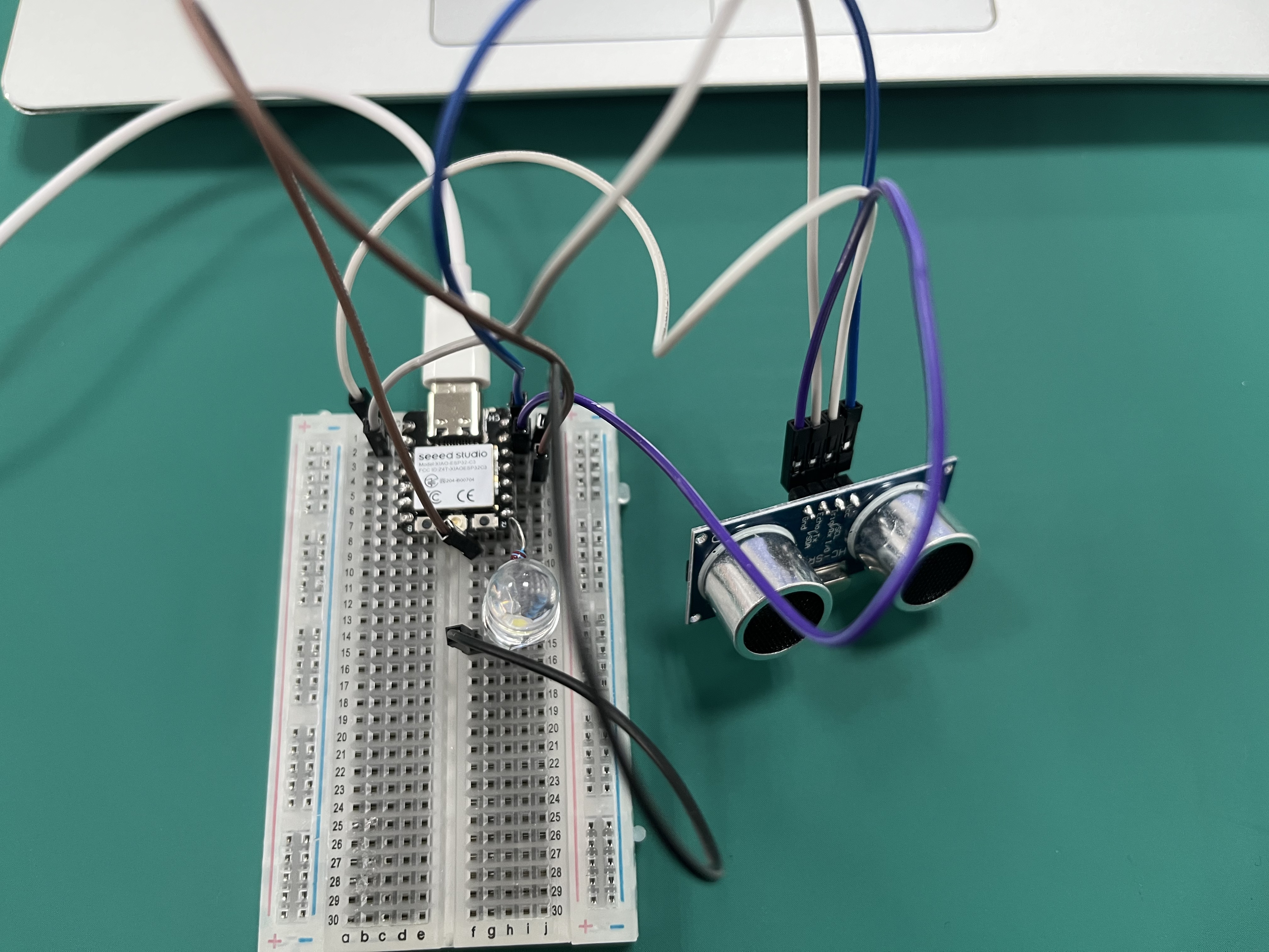
Circuit Diagram
Components Required:
- Xiao esp32c3
- HC-SR04 Ultrasonic Sensor
- LED + 220Ω resistor
- Breadboard & jumper wires
Code Implementation
#define TrigPin A0
#define EchoPin A1
int count = 0;
long duration;
void setup() {
Serial.begin(115200);
pinMode(TrigPin, OUTPUT);
pinMode(EchoPin, INPUT);
digitalWrite(TrigPin, LOW);
delay(1);
pinMode (D10, OUTPUT);
}
void loop() {
Serial.println(count++);
Serial.println(getDistance());
Serial.println("");
Serial.println("");
delay(1000);
int distance= getDistance();
if (distance>200){
digitalWrite(D10, HIGH);
}
else {
digitalWrite(D10, LOW);
}
}
long getDistance() {
digitalWrite(TrigPin,LOW);
delayMicroseconds(2);
digitalWrite(TrigPin, HIGH);
delayMicroseconds(10);
digitalWrite(TrigPin,LOW);
duration = pulseIn(EchoPin,HIGH);
return duration * 0.34029 /2;
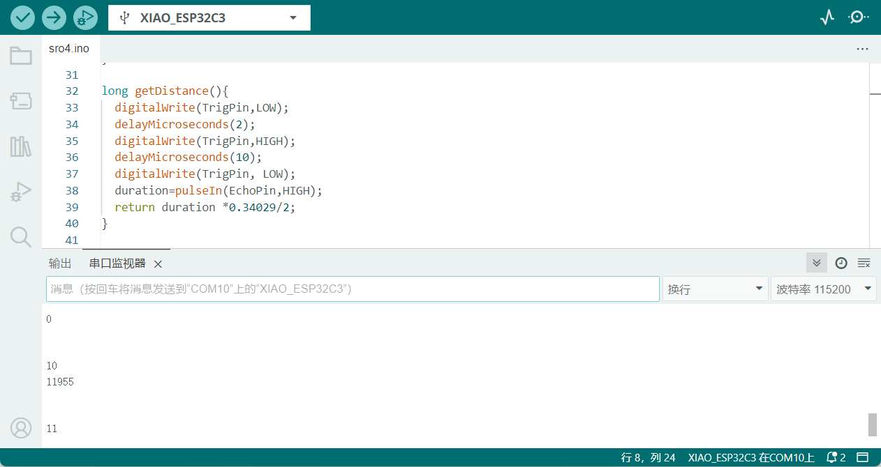
}System Behavior
Expected Effects:
- Serial Output (115200 baud): Cycle counter increments every second Real-time distance measurements in centimeters Example: Cycle: 42
Distance: 215 cm - LED Indication: Illuminates continuously when distance > 200cm Turns off when objects move within 200cm range
- Measurement Characteristics: Accuracy: ±3mm (within 100cm) Maximum detection: ~400cm Sampling rate: 1Hz
5.Homwork
Project Definition
This Arduino project implements a simple IoT Temperature Monitoring Station that utilizes an DHT11 temperature and humidity sensor and an LCD display. It demonstrates:
Real-time temperature/humidity data acquisition (0-50°C ±2°C, 20-90% RH ±5%) Dual-unit temperature display (Celsius/Fahrenheit) Graphical user interface with color-coded parameters Error detection and visual alerts SPI communication protocol implementation
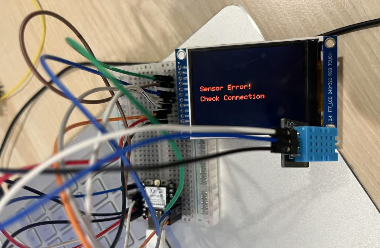
Wiring Diagram
Required Components:
XIAO ESP32C3 ILI9341 TFT LCD (240x320) DHT11 Temperature/Humidity Sensor Breadboard & jumper wires 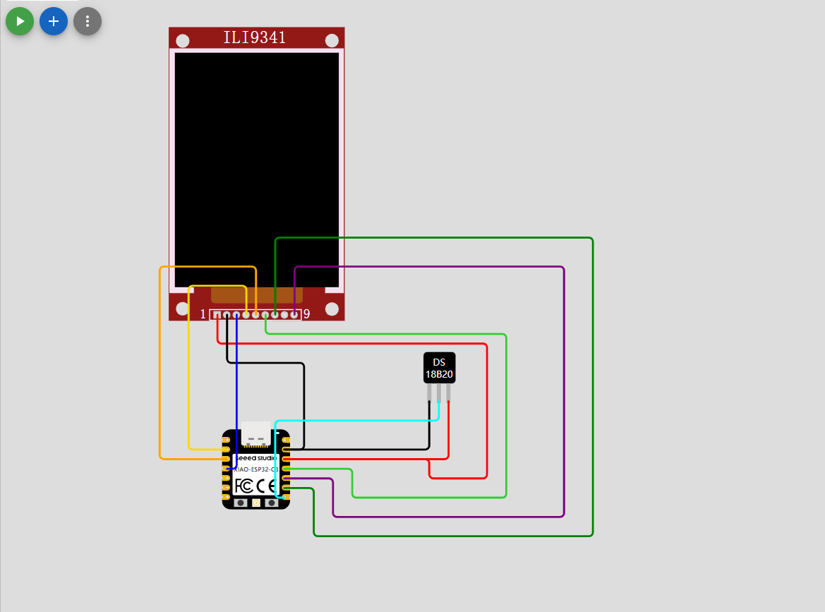
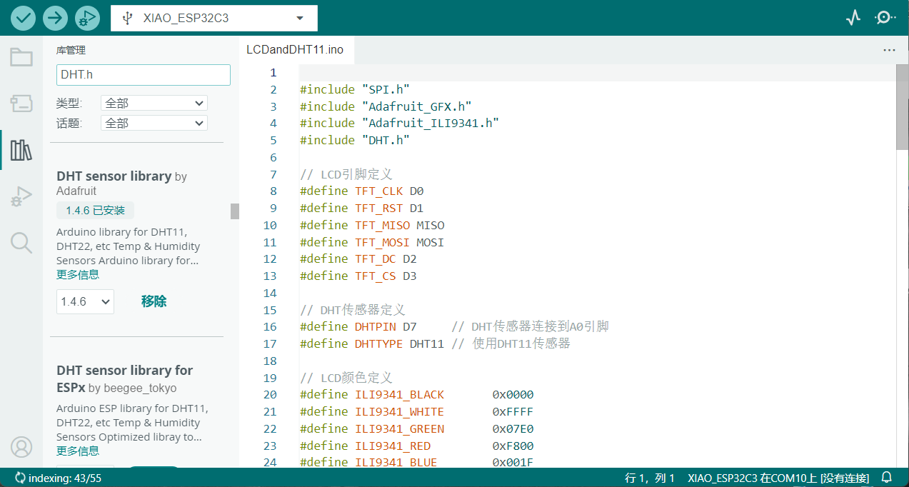
Methods to Install Arduino Libraries
Launch Arduino IDE
- Open the development environment (version 1.8.19+ recommended)
Access Library Manager
- Navigate to: Sketch > Include Library > Manage Libraries...
Search & Install
- Type library name in search bar (e.g., "Wire")
- Select desired version from dropdown
- Click "Install" (Internet required)
 Verification
 - Installed libraries appear under: File > Examples > [Library Name]
Code Implementation
#include "SPI.h"
#include "Adafruit_GFX.h"
#include "Adafruit_ILI9341.h"
#include "DHT.h"

// LCD pin definitions
#define TFT_CLK D0
#define TFT_RST D1
#define TFT_MISO MISO
#define TFT_MOSI MOSI
#define TFT_DC D2
#define TFT_CS D3

// DHT sensor definitions
#define DHTPIN D7     // DHT sensor connected to pin D7
#define DHTTYPE DHT11 // Using DHT11 sensor

// LCD color definitions
#define ILI9341_BLACK       0x0000
#define ILI9341_WHITE       0xFFFF
#define ILI9341_GREEN       0x07E0
#define ILI9341_RED         0xF800
#define ILI9341_BLUE        0x001F
#define ILI9341_YELLOW      0xFFE0

// Initialize objects
Adafruit_ILI9341 tft = Adafruit_ILI9341(TFT_CS, TFT_DC, TFT_MOSI, TFT_CLK, TFT_RST, TFT_MISO);
DHT dht(DHTPIN, DHTTYPE);

void setup() {
  Serial.begin(9600);
  Serial.println("Temperature and Humidity Display");

  // Initialize LCD
  tft.begin();
  tft.setRotation(1); // Optional: adjust screen orientation (0-3)

  // Initialize DHT sensor
  dht.begin();

  // Display initial screen
  tft.fillScreen(ILI9341_BLACK);
  tft.setTextColor(ILI9341_WHITE);
  tft.setTextSize(2);
  tft.setCursor(20, 100);
  tft.println("Initializing...");
  delay(2000);
}

void loop() {
  // Read sensor data
  float humidity = dht.readHumidity();
  float tempC = dht.readTemperature();      // Celsius
  float tempF = dht.readTemperature(true);  // Fahrenheit

  // Check if data is valid
  if (isnan(humidity) || isnan(tempC) || isnan(tempF)) {
    displayError();
    delay(2000);
    return;
  }

  // Display data
  displayData(humidity, tempC, tempF);
  delay(2000);  // Update every 2 seconds
}

void displayData(float humidity, float tempC, float tempF) {
  // Clear screen
  tft.fillScreen(ILI9341_BLACK);

  // Set title
  tft.setTextColor(ILI9341_YELLOW);
  tft.setTextSize(3);
  tft.setCursor(20, 20);
  tft.println("Weather Station");

  // Display humidity
  tft.setTextColor(ILI9341_BLUE);
  tft.setTextSize(2);
  tft.setCursor(20, 70);
  tft.print("Humidity: ");
  tft.print(humidity);
  tft.println(" %");

  // Display Celsius temperature
  tft.setTextColor(ILI9341_RED);
  tft.setCursor(20, 100);
  tft.print("Temp: ");
  tft.print(tempC);
  tft.println(" *C");

  // Display Fahrenheit temperature
  tft.setTextColor(ILI9341_GREEN);
  tft.setCursor(20, 130);
  tft.print("Temp: ");
  tft.print(tempF);
  tft.println(" *F");
}

void displayError() {
  // Display error message
  tft.fillScreen(ILI9341_BLACK);
  tft.setTextColor(ILI9341_RED);
  tft.setTextSize(2);
  tft.setCursor(20, 100);
  tft.println("Sensor Error!");
  tft.setCursor(20, 130);
  tft.println("Check Connection");
}
Expected Effect
perational Effects:
Display Output: Yellow header "Weather Station" Blue humidity reading (0-100% RH) Red Celsius (0-50°C) / Green Fahrenheit Coordinated layout prevents screen tearing
Error Handling: Sensor Error!
Check Connection
Performance Metrics: Sampling Rate: 0.5Hz (conserves power) SPI Throughput: 15MHz (smooth rendering) Accuracy: ±2°C (temp), ±5% (humidity)