Interface and Application Programming
This week, I learned how to use Processing, a visual programming language widely used for creative coding and interactive applications. I also explored how to establish real-time communication between Processing and Arduino, enabling data exchange and synchronized interaction. By using serial communication, I was able to visualize sensor input from Arduino in Processing and create simple interactive graphics that respond to hardware events. This integration helped me understand the fundamentals of software-hardware interaction in physical computing projects.
1.Processing
Processing is a flexible software sketchbook and a language for learning how to code within the context of the visual arts. Since 2001, Processing has promoted software literacy within the visual arts and visual literacy within technology. There are tens of thousands of students, artists, designers, researchers, and hobbyists who use Processing for learning and prototyping.Download Processing in this website:https://processing.org/download
Using Procssing to control Arduino
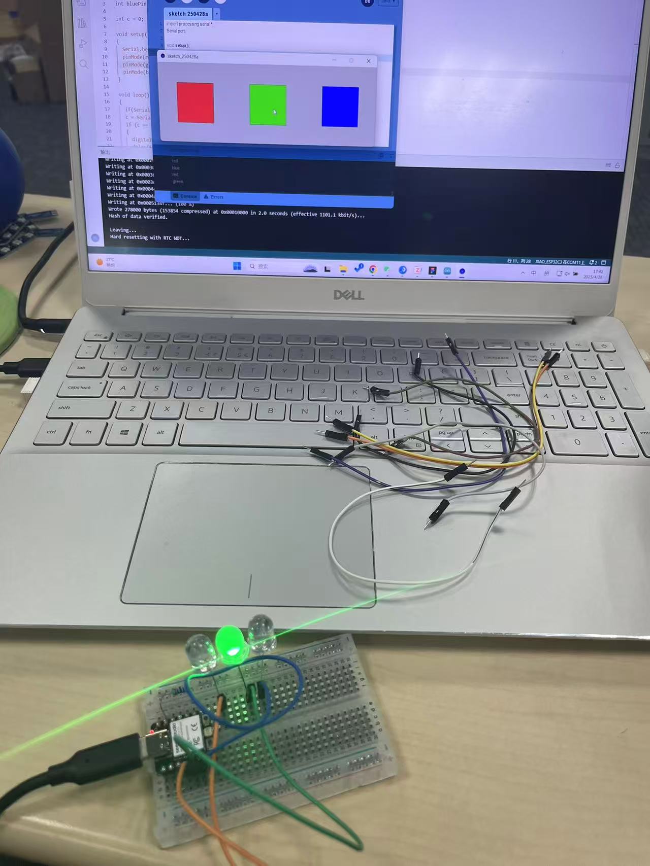
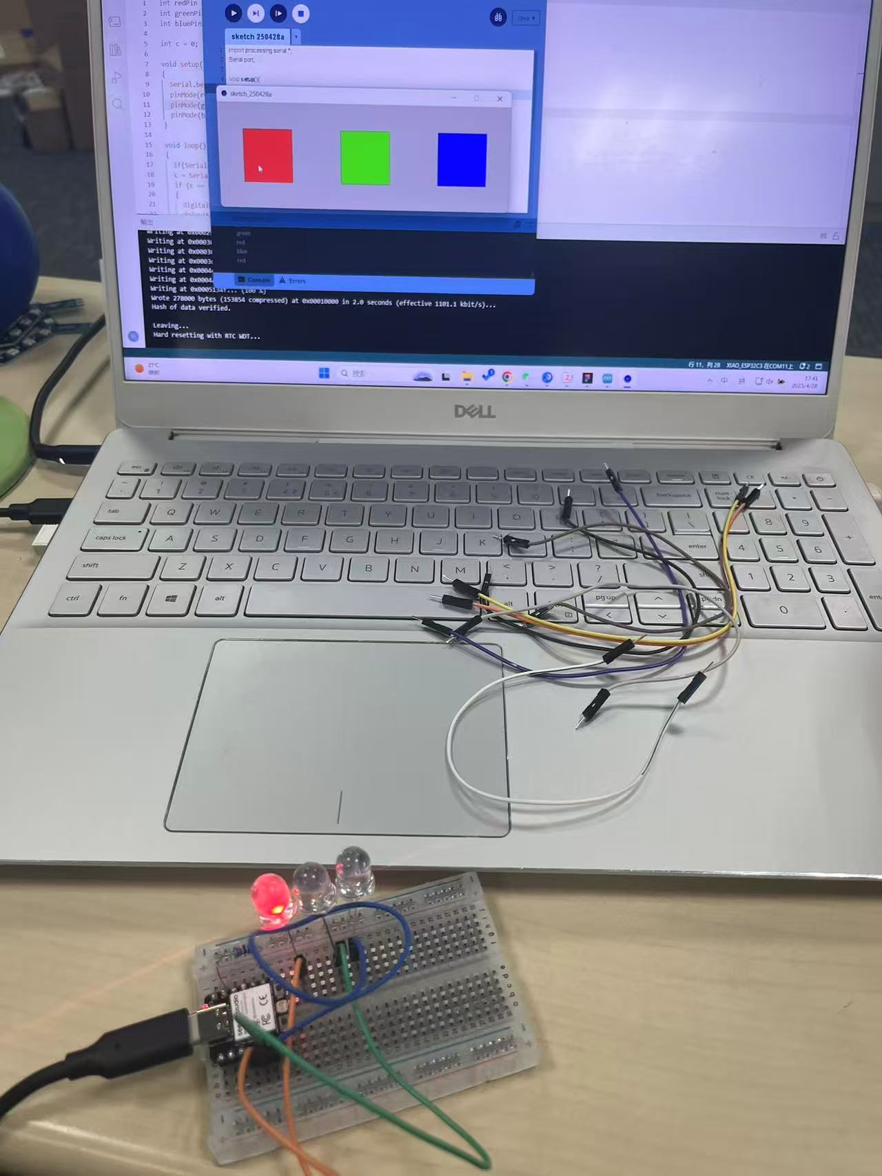
This project demonstrates how to use Processing (a Java-based visual programming IDE) to control the RGB LEDs on an Arduino through serial communication. Each colored rectangle displayed on the Processing canvas sends a different character to the Arduino when clicked, triggering the corresponding LED.
Arduino Code:
int redPin = 3;
int greenPin = 4;
int bluePin = 5;
int c = 0;

void setup()
{
  Serial.begin(9600);
  pinMode(redPin, OUTPUT);
  pinMode(greenPin, OUTPUT);
  pinMode(bluePin, OUTPUT);
}

void loop()
{
  if (Serial.available())
  {
    c = Serial.read();
    if (c == 97)  // 'a'
    {
      digitalWrite(redPin, HIGH); delay(500); digitalWrite(redPin, LOW);
    }
    if (c == 98)  // 'b'
    {
      digitalWrite(greenPin, HIGH); delay(500); digitalWrite(greenPin, LOW);
    }
    if (c == 99)  // 'c'
    {
      digitalWrite(bluePin, HIGH); delay(500); digitalWrite(bluePin, LOW);
    }
  }
}
Processing Code:
import processing.serial.*;
Serial port;
void setup(){
port = new Serial(this, "COM5", 9600); // Replace with your actual COM port
size(600, 200);
}
void draw(){
fill(255, 0, 0); rect(50, 50, 100, 100); // Red
fill(0, 255, 0); rect(250, 50, 100, 100); // Green
fill(0, 0, 255); rect(450, 50, 100, 100); // Blue
}
void mouseClicked(){
if (mouseX >= 50 && mouseX <= 150 && mouseY >= 50 && mouseY <= 150) {
println("Red clicked");
port.write('a');
}
else if (mouseX >= 250 && mouseX <= 350 && mouseY >= 50 && mouseY <= 150) {
println("Green clicked");
port.write('b');
}
else if (mouseX >= 450 && mouseX <= 550 && mouseY >= 50 && mouseY <= 150) {
println("Blue clicked");
port.write('c');
}
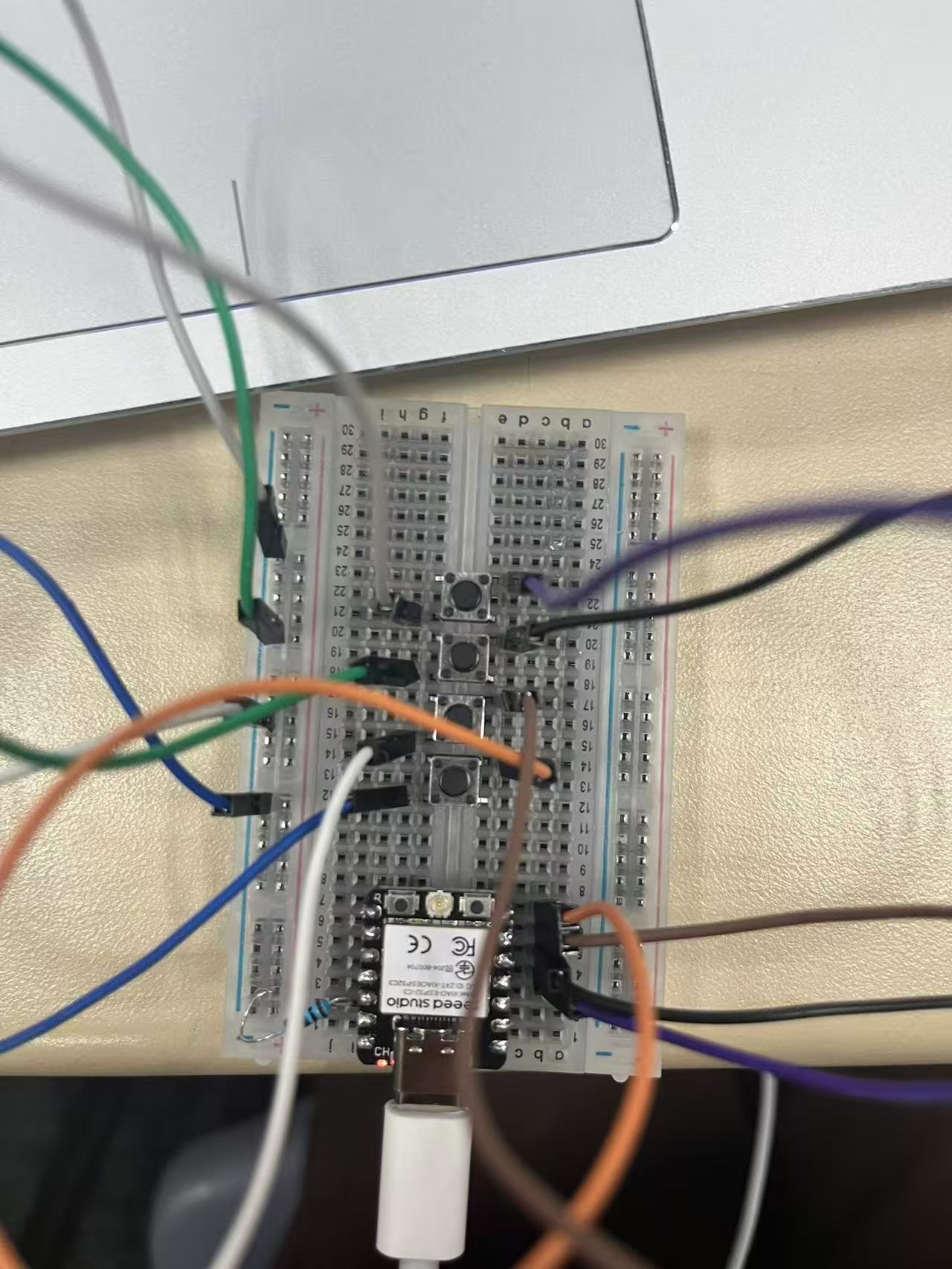
}Connect each LED (with a 220Ω resistor in series) to the respective digital pin and GND. 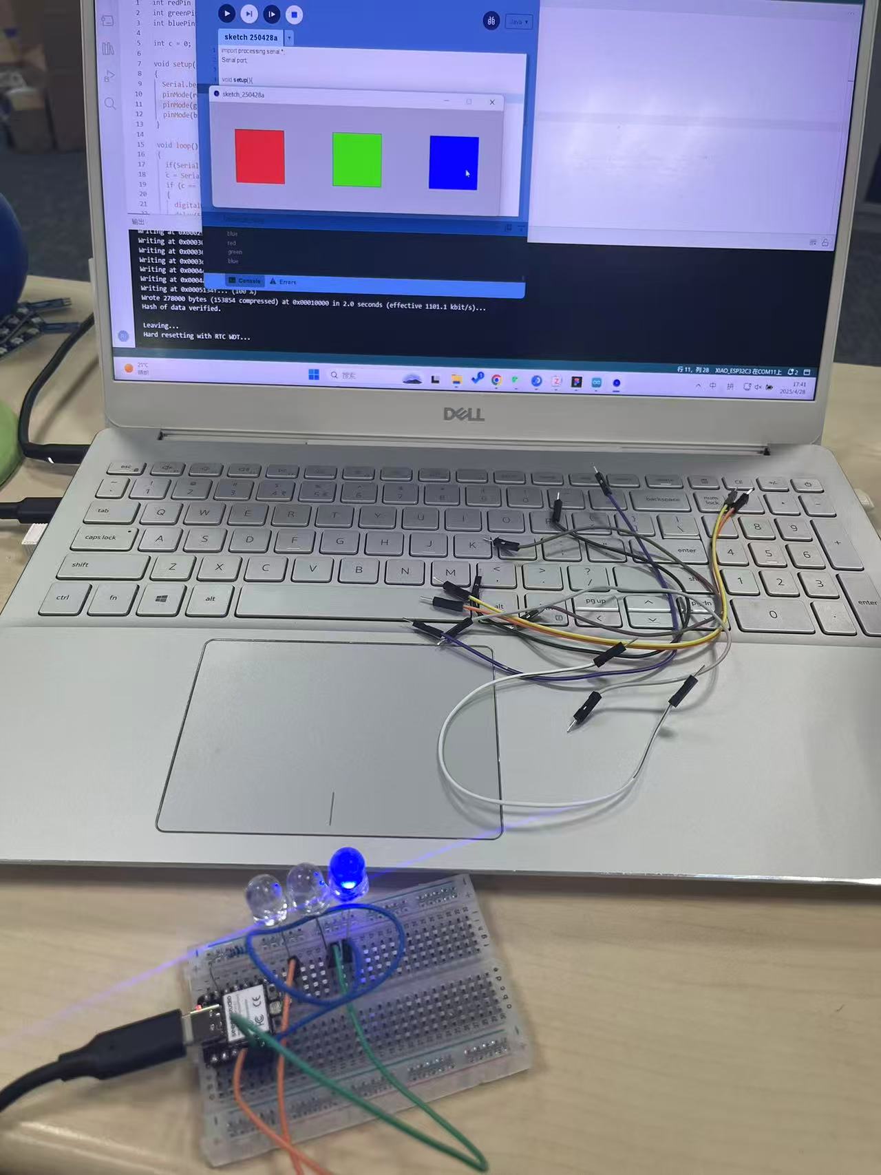
Using Arduino to control Processing
This document describes a system where an Arduino board reads input from four push buttons and sends corresponding serial commands to a Processing sketch. The Processing sketch interprets these commands to move a red circle on a graphical display.
Arduino Code:
int upPin = 3;
int downPin = 4;
int leftPin = 5;
int rightPin = 6;
int up1, down1, left1, right1;

void setup() {
  pinMode(upPin, INPUT_PULLUP);
  pinMode(downPin, INPUT_PULLUP);
  pinMode(leftPin, INPUT_PULLUP);
  pinMode(rightPin, INPUT_PULLUP);
  Serial.begin(9600);
}

void loop() {
  up1 = digitalRead(upPin);
  down1 = digitalRead(downPin);
  left1 = digitalRead(leftPin);
  right1 = digitalRead(rightPin);

  if (up1 == 0) {
    delay(500); // Debounce delay
    Serial.write("a"); // Send 'a' for "up"
  }
  else if (down1 == 0) {
    delay(500);
    Serial.write("b"); // Send 'b' for "down"
  }
  else if (left1 == 0) {
    delay(500);
    Serial.write("c"); // Send 'c' for "left"
  }
  else if (right1 == 0) {
    delay(500);
    Serial.write("d"); // Send 'd' for "right"
  }
}
Processing Code:
import processing.serial.*;
Serial port;
int a = 300; // Initial X-coordinate
int b = 300; // Initial Y-coordinate

void setup() {
  size(600, 600);
  background(200, 200, 200); // Gray background
  fill(255, 0, 0); // Red color
  ellipse(a, b, 30, 30); // Draw initial circle
  port = new Serial(this, "COM4", 9600); // Connect to Arduino
}

void draw() {
  while (port.available() > 0) {
    char input = port.readChar(); // Read serial input
    switch(input) {
      case 'a': // Up
        background(200, 200, 200);
        fill(255, 0, 0);
        b -= 20; // Move circle up
        ellipse(a, b, 30, 30);
        break;

      case 'b': // Down
        background(200, 200, 200);
        fill(255, 0, 0);
        b += 20; // Move circle down
        ellipse(a, b, 30, 30);
        break;

      case 'c': // Left
        background(200, 200, 200);
        fill(255, 0, 0);
        a -= 20; // Move circle left
        ellipse(a, b, 30, 30);
        break;

      case 'd': // Right
        background(200, 200, 200);
        fill(255, 0, 0);
        a += 20; // Move circle right
        ellipse(a, b, 30, 30);
        break;

      default:
        break;
    }
  }
}
This project demonstrates serial communication between Arduino and Processing, allowing physical button inputs to control graphical elements.