Electronic design
In this class, I learned PCB related knowledge, downloaded Autodesk Fusion and Jialichuan EDA, and drew PCB board.
1.Autodesk Fusion 360
Download and install
Download the Installer
Visit the official Autodesk Fusion 360 website: https://www.autodesk.com/products/fusion-360 and click "Download Free Trial".
Select your operating system (Windows/macOS) and save the installer file (approx. 700MB-1GB).
Run the Installer
Double-click the downloaded file (.exe for Windows or .dmg for macOS). Follow the on-screen instructions to complete the installation. Choose a non-system drive for installation if possible.
Launch Fusion 360
After installation, open the software. You'll be prompted to sign in with an Autodesk ID.
Student Registration Guide
Create an Autodesk ID
If you don't have an Autodesk account: Click "Need an Autodesk ID?" during the sign-in process. Provide your educational email (e.g., @edu) or personal email and complete registration.
Apply for Educational License
Visit the Autodesk Education Portal: https://www.autodesk.com/education. Search for "Fusion 360" and select "Get Product". 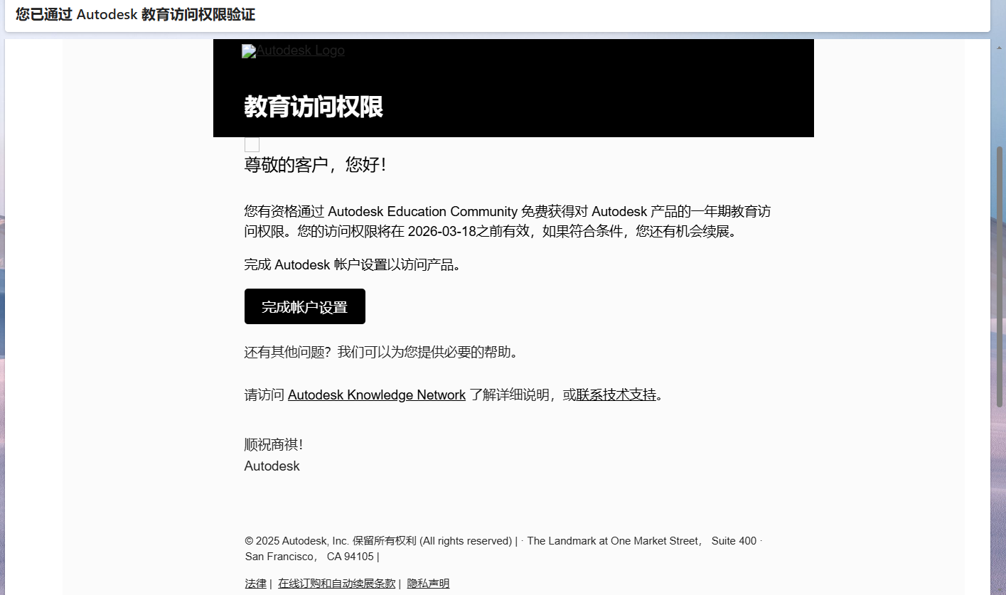 Verify your student status by: Uploading a valid student ID or enrollment letter. Providing school name and graduation date.
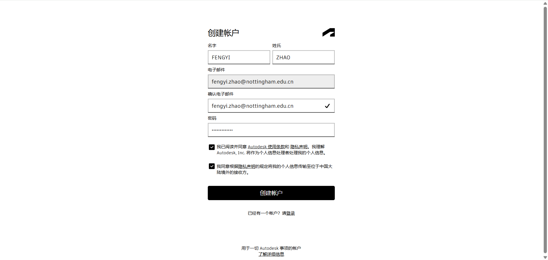
Activate Educational Access
Once approved, log into Fusion 360 using your Autodesk ID. The software will automatically switch to the educational license (valid for 1-3 years)
2.JiaLiChuang EDA
Here’s a guide for designing the PCB shown using JiaLiChuang EDA (JLCEDA).
Create a New Project
Launch JiaLiChuang EDA and click "File" > "New Project".
Name the project (e.g., "Xiao_ESP32C3_PCB") and select "PCB_New Project" from the workspace panel. 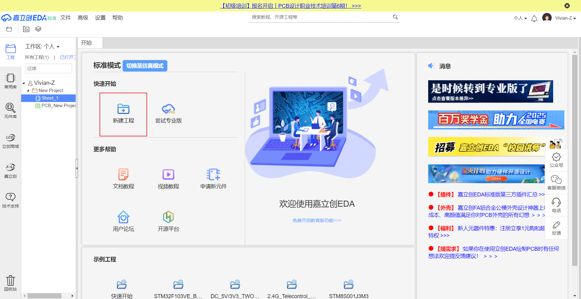
Add Components
Place critical components from the library:
Xiao ESP32-C3: Search for "Xiao ESP32-C3" in the component library.
Switch: Add an SPST switch.
Resistor: Select a 220Ω resistor.
LED: Choose a standard LED.
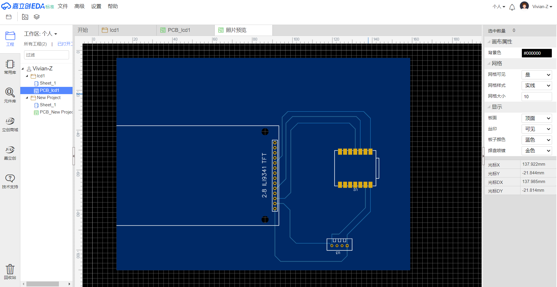
Arrange components as shown in this image:
Position the Xiao ESP32-C3 centrally. Place the switch near the board edge (e.g., labeled SW1). Connect the resistor to the LED and Xiao's GPIO pin (e.g., DIO11 or DIO12). 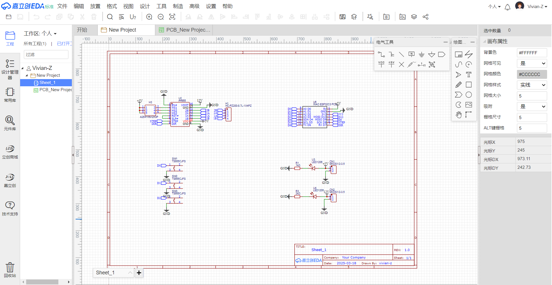
Draw Connections
Use the Wire Tool to create traces:
Connect the Xiao's 3V3 pin to the switch and LED's anode (via resistor). Link the switch to GND (ground plane). Route GND connections to all components (use the GND symbol). 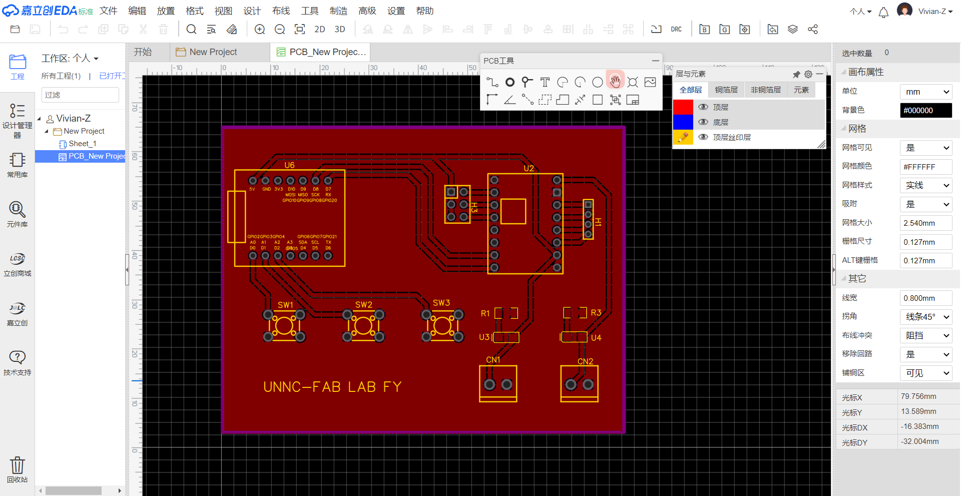
Validate the Design
Run Design Rule Check (DRC):
Check for unconnected nets, short circuits, or clearance errors. Verify component alignment and spacing using the Measurement Tool.
Export Manufacturing Files
Click "File" > "Export" and generate:
Gerber Files (for PCB fabrication).
Bill of Materials (BOM) for component procurement.
Save the project locally or to the cloud ("Personal" workspace). 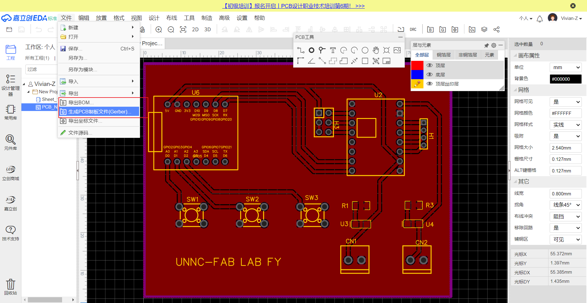
3.Ordering custom boards via LCSC (Shenzhen Jiali Chuang Electronic Commerce Co., Ltd.)
Upload Files to LCSC/JLCPCB
Visit JLCPCB Order Page:
Go to https://jlcpcb.com and click “Instant Quote”.  Upload Gerber File:
Drag and drop the .zip file into the upload area. Wait for automatic file validation (green checkmark = success).
Configure PCB Specifications:
Quantity: Select number of boards (e.g., 5-50). Layers: Confirm layer count (e.g., 2 layers). Dimensions: Verify board size (auto-detected from Gerber). Material: Choose FR-4 standard. Thickness: Default 1.6mm (adjust if needed). Surface Finish: Select HASL (lead-free) or ENIG (for better durability). Silkscreen/Color: Choose white silkscreen on green solder mask (default). 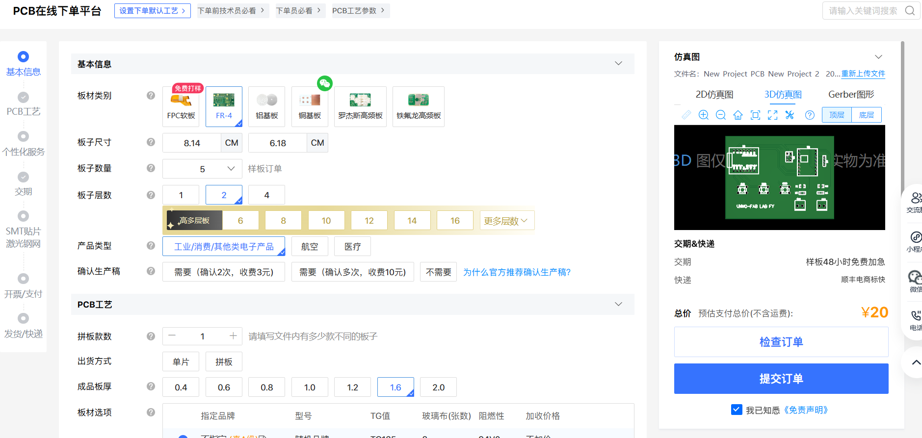 4.Add SMT Assembly (Optional):
Toggle “SMT Assembly” if components need mounting. Upload BOM and Pick-and-Place files. Confirm LCSC part numbers match your design.
Review and Confirm Order
Check Gerber Preview:
Use the interactive viewer to verify traces, drills, and silkscreen alignment.
Calculate Cost:
The quote updates automatically based on quantity and options.
Shipping & Payment:
Select shipping method (e.g., DHL, FedEx, or standard post). Enter delivery address. Pay via credit card, PayPal, or Alipay.
Submit Order:
Click "Save to Cart" and confirm payment. 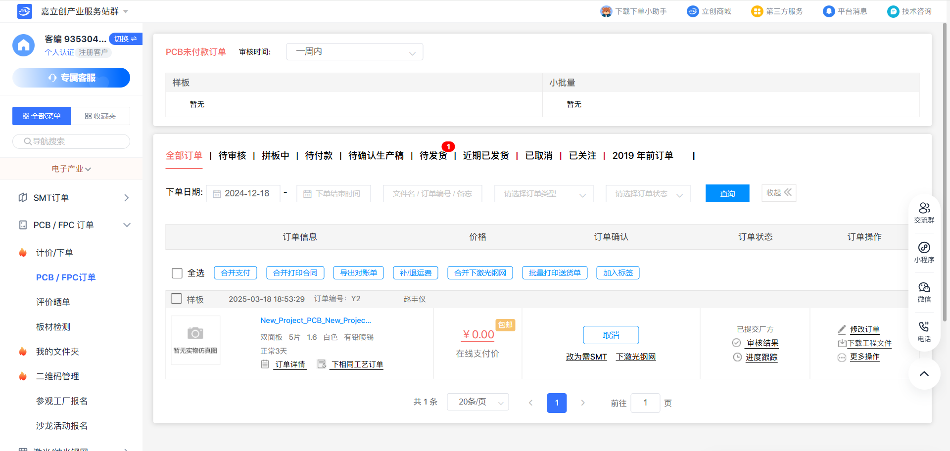
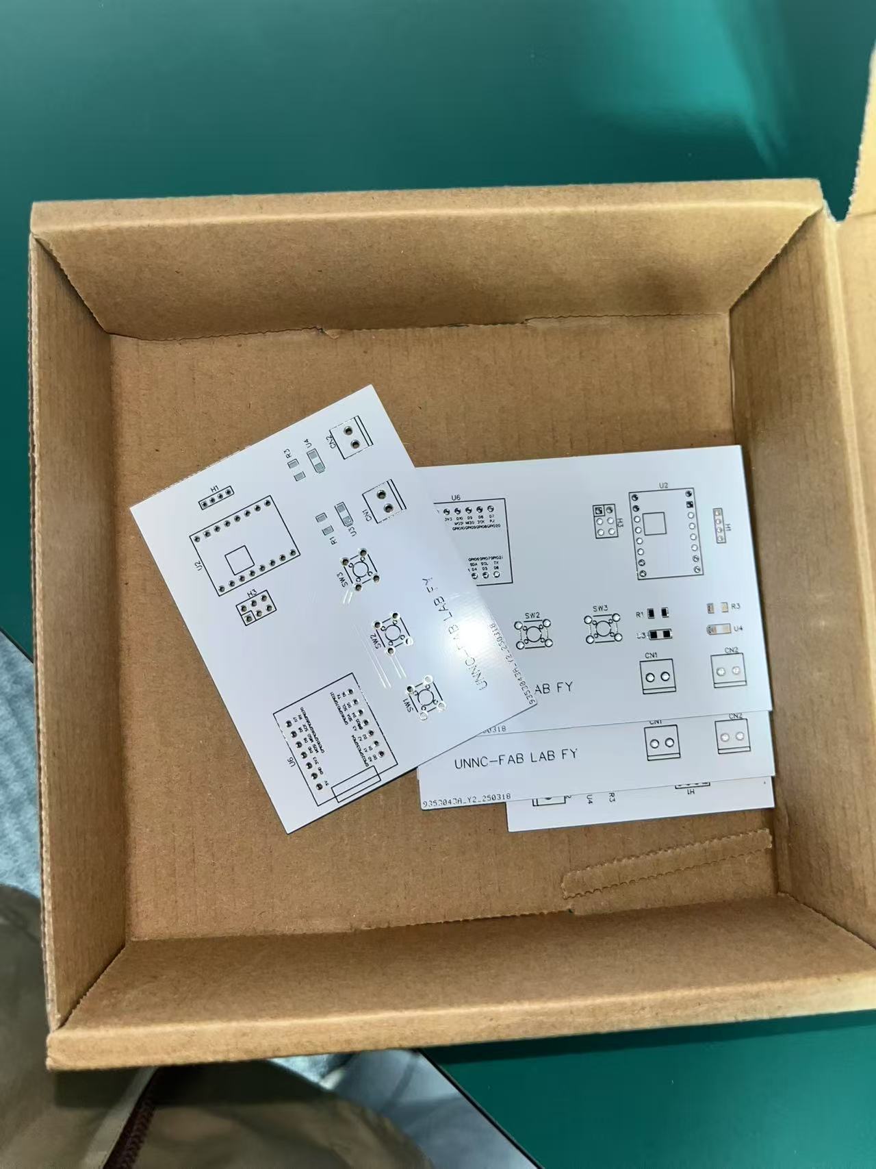
4.Homework
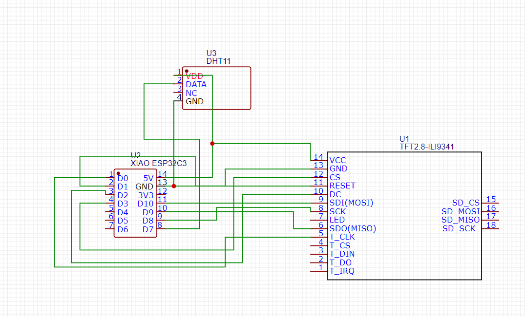
This project involved designing a custom PCB using JLCPCB to optimize the circuitry for an IoT environmental monitoring system. The board integrates the following key components:
XIAO ESP32-C3 (Wi-Fi/BLE-enabled microcontroller) ILI9341 TFT LCD (240×320 resolution) DHT11 (Temperature & Humidity Sensor) The PCB replaces a breadboard prototype, improving reliability and reducing wiring complexity.