CNC Manufacture
This week, I focused on CNC manufacturing and PCB design. Using Fusion 360, I designed a custom circuit board, then attempted to mill it with a CNC machine. After fabrication, I practiced soldering components onto the PCB to test functionality.
1. CNC Introduction
Image source:https://www.techtarget.com/searcherp/definition/computer-numerical-control-CNCWhat is CNC?
CNC (Computer Numerical Control) is a manufacturing process where pre-programmed computer software controls the movement of machinery and tools. It is widely used for cutting, milling, drilling, and shaping materials like metal, wood, and plastic with high precision.
How CNC Works
- Design Phase: A 3D model (e.g., created in Fusion 360) is converted into G-code, a language that instructs the CNC machine.
- Setup: The material is secured, and the correct tools (end mills, drills) are installed.
- Automated Machining: The CNC machine follows the G-code to carve the design autonomously.
Advantages of CNC
• Precision: Achieves tight tolerances (up to ±0.001 inches).
• Repeatability: Perfect for mass production of identical parts.
• Complexity: Capable of intricate designs impossible with manual tools.
Applications
• PCB milling (like this week's project).
• Aerospace components, automotive parts, and custom prototypes.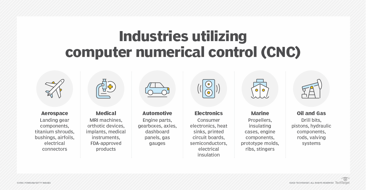
2.Fusion 360 PCB Design & Roland CNC engraving process
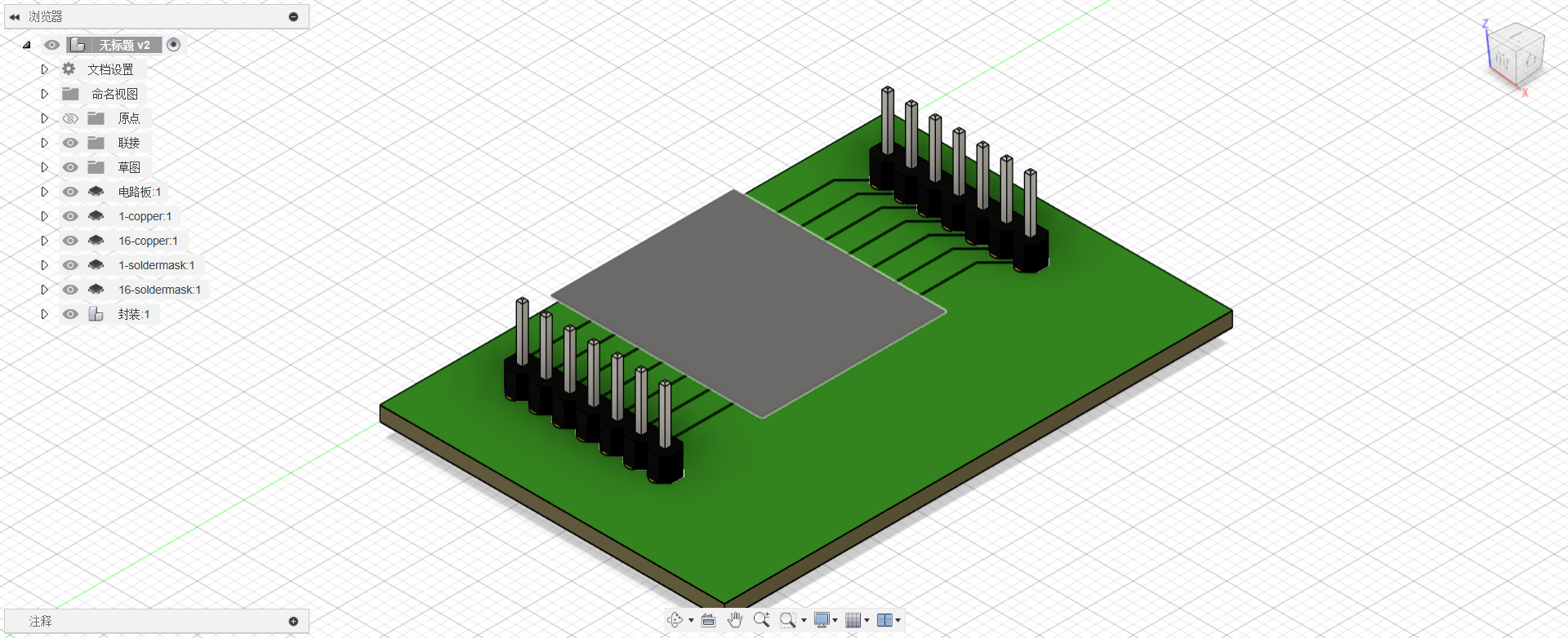
Fusion 360 PCB Design
• Open Fusion 360 and create a new PCB design under the Electronics workspace.
• Place a XIAO ESP32C3.
• Place two 7-pin headers (PINHD-1X07)
• Route signal traces (green lines) between pins, matching the connections shown. 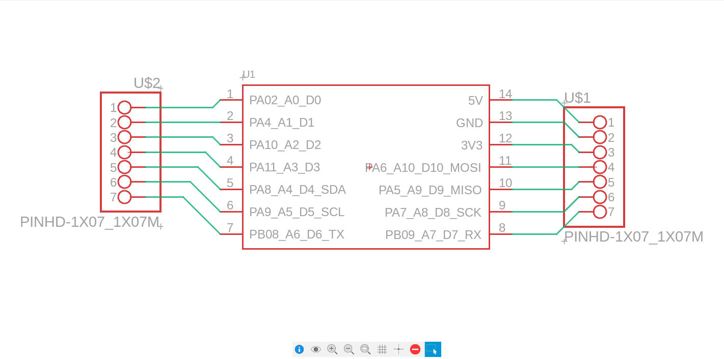
Export Gerber & STL Files
• Export the design as Gerber RS-274X files (include copper, silkscreen, and drill layers).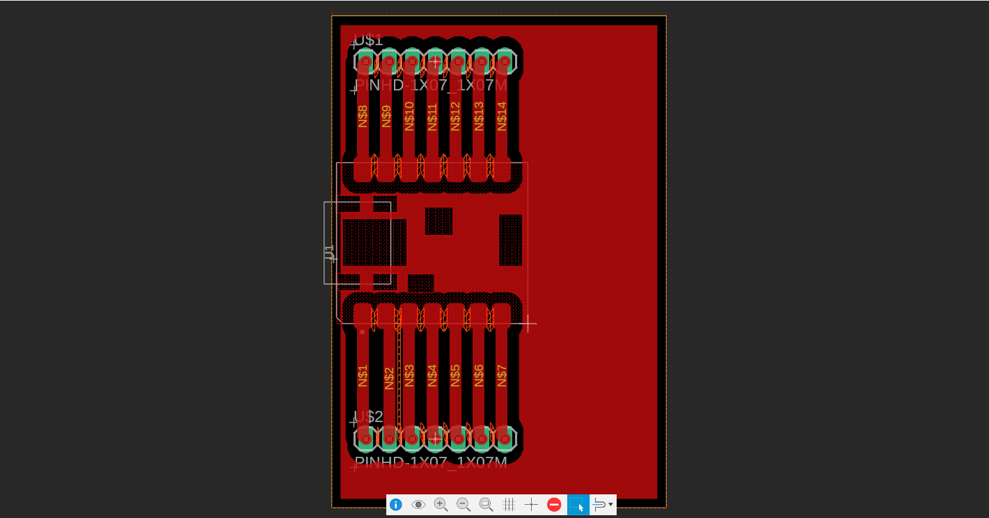
 • Generate an STL file for 3D preview (select only the top copper layer).
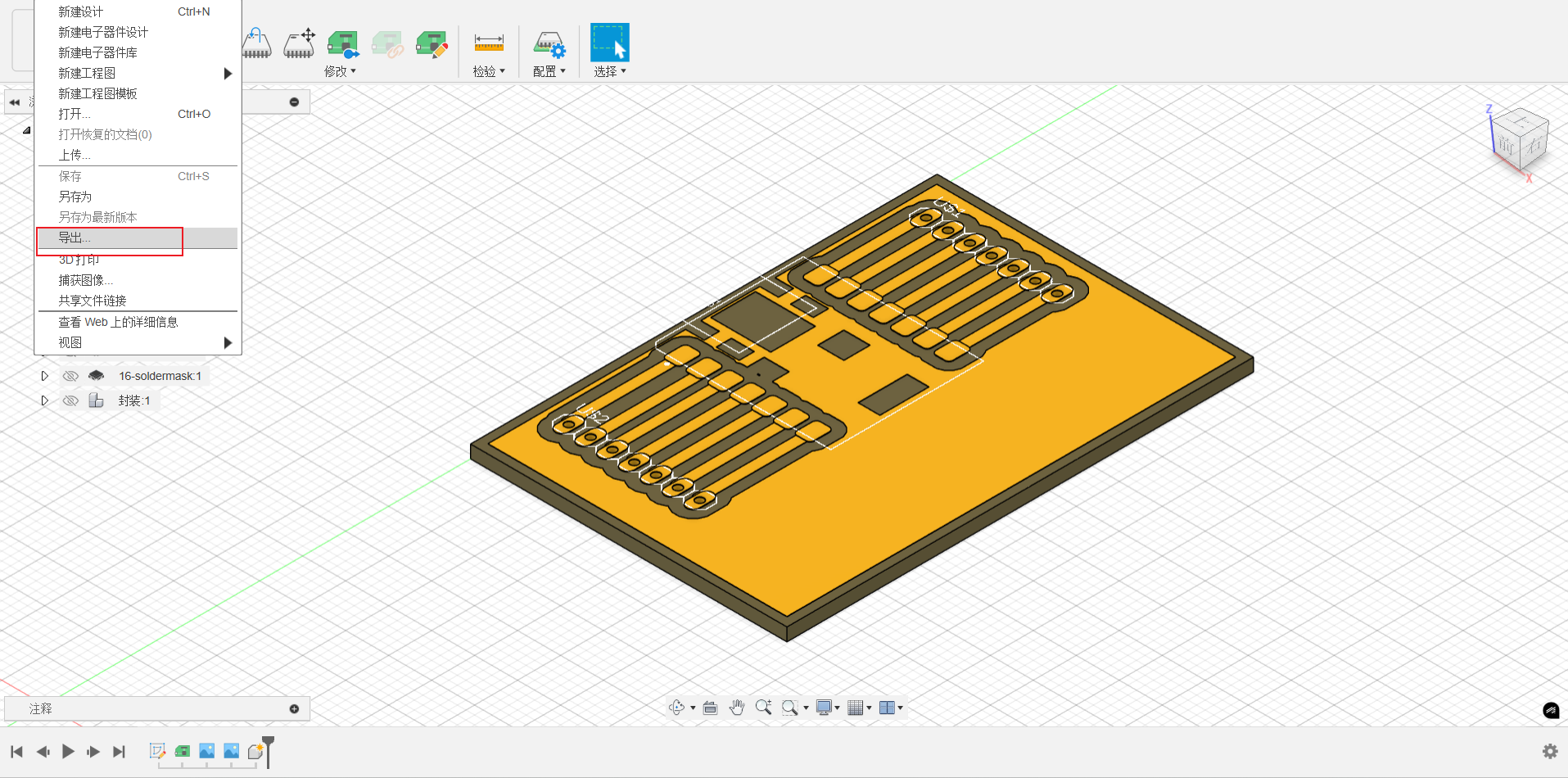
Prepare for Roland CNC
To manufacture the PCB, the Roland software was download (https://www.rolanddga.com/).
• Use FlatCAM or KiCad to convert Gerber files to Roland-compatible .rol format.
• Set CNC parameters:
• Tool diameter: 0.2mm
• Cut depth: 0.05mm (copper layer)
• Feed rate: 30mm/s
CNC Milling Process
• Secure the copper-clad board to the Roland CNC bed.
• Load the .rol file in VPanel (Roland software) and set X/Y/Z origins.
• Run a test path to verify alignment, then start milling.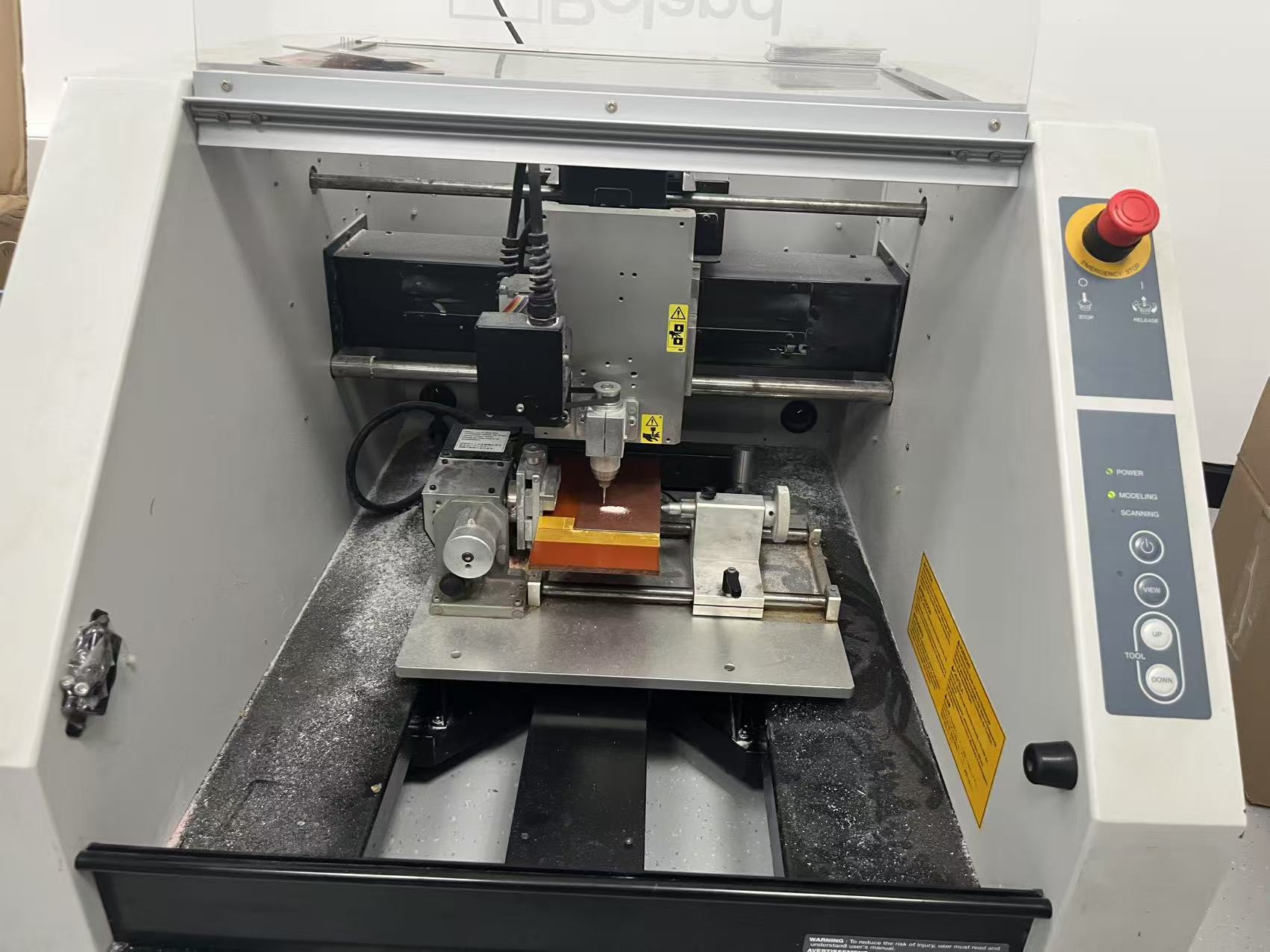 • Post-process: Clean the board and check traces for continuity.
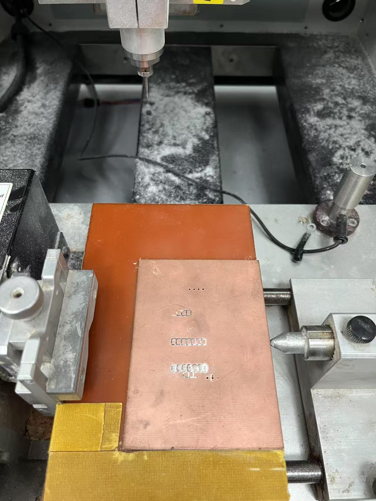 Soldering & Testing
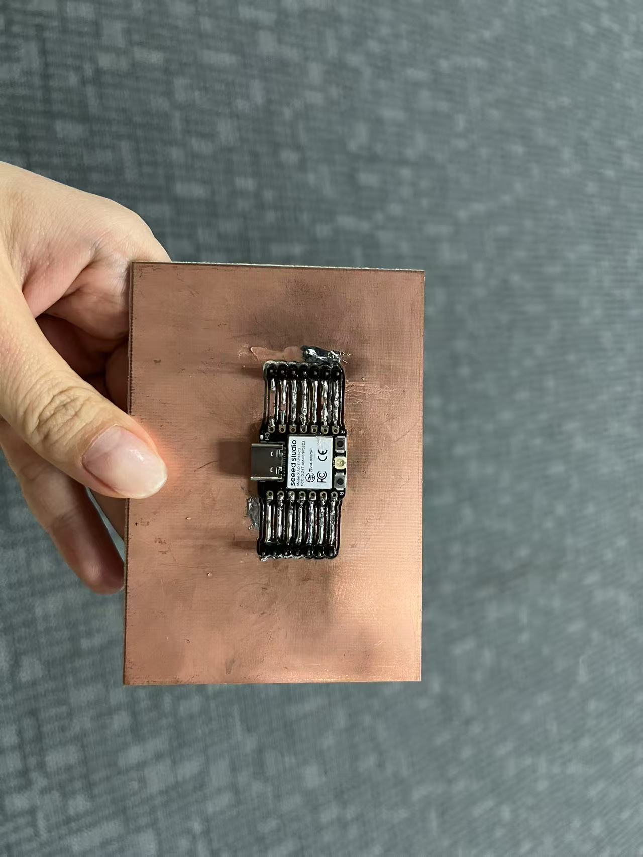
• Solder components (headers, STM32 MCU) following the pinout labels.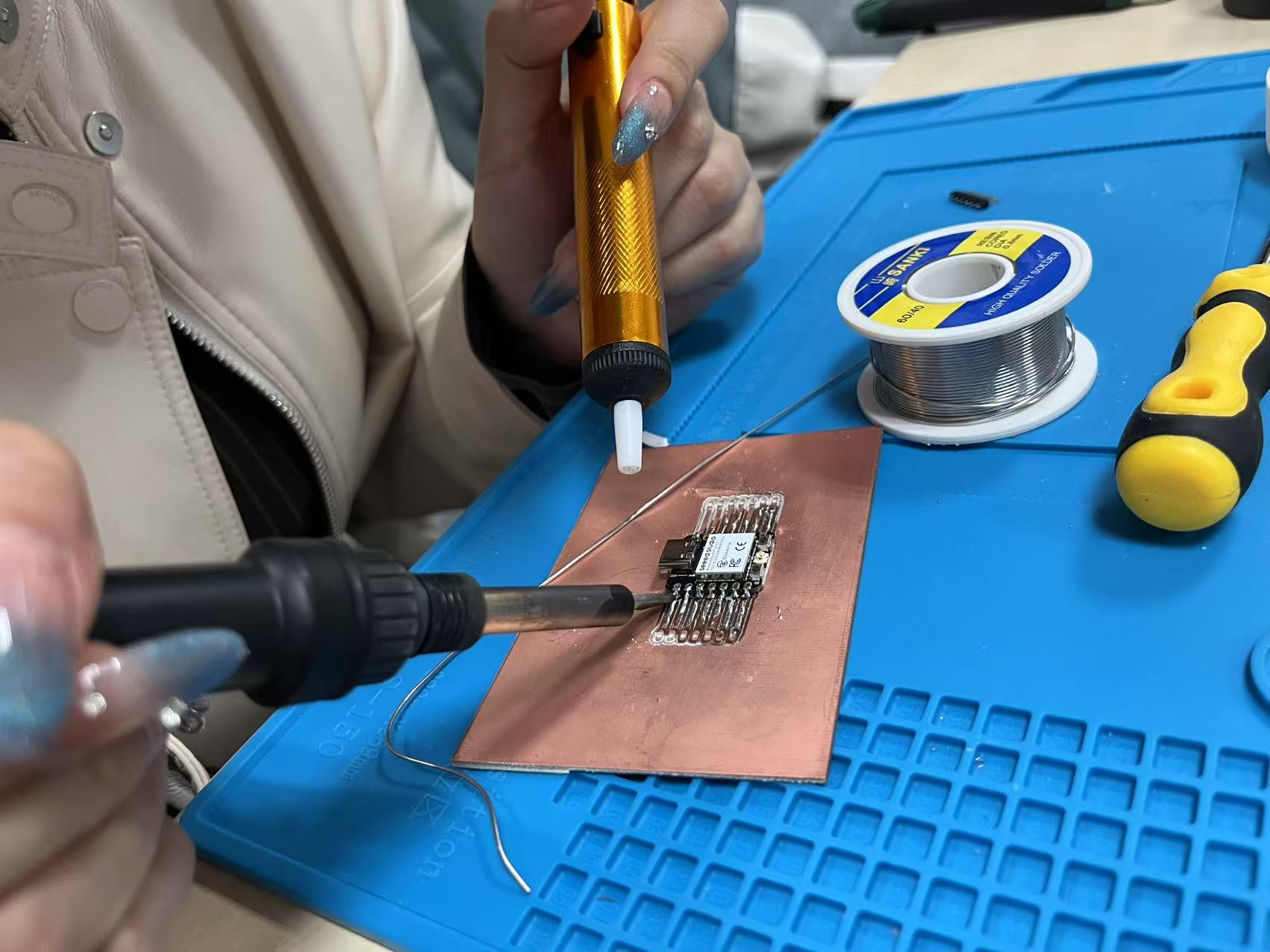 • Verify connections with a multimeter (check for shorts between
 5V and GND).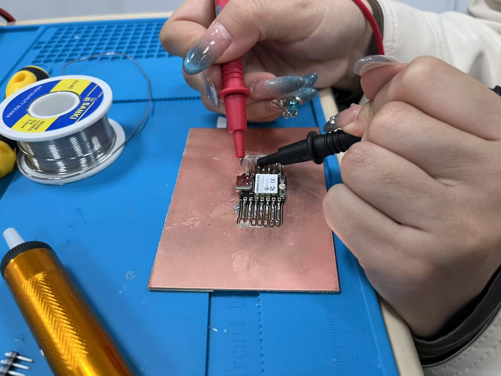 Key Notes
• Design symmetry: Mirror the header placements as shown in the image.
• Signal grouping: Keep power (5V, GND, 3V3) and communication lines (UART, I2C, SPI) clearly separated.
• Safety: Wear goggles during CNC operation and ensure proper ventilation.