Computer Aid Design - 2D & 3D
This week focused on developing core Fusion 360 skills:
Practiced 3D modeling techniques and basic parametric design workflows to create adaptable components.
Conducted motion studies with contact sets and joint linkages, visualizing results through animated demonstrations.
Explored plugin integration to enhance design capabilities and streamline workflows.
Generated detailed engineering drawings for a mechanical part, applying standard documentation practices.
The sessions strengthened proficiency in parametric design, motion analysis, and technical documentation within Fusion 360. 3D Design with Autodesk Fusion360
1.Fusion 360
Fusion 360 is a cloud-based 3D CAD, CAM, and CAE tool developed by Autodesk. It is widely used for product design, engineering, and manufacturing. Fusion 360 integrates various design processes into a single platform, allowing users to create 3D models, simulate mechanical behavior, perform analysis, and generate toolpaths for manufacturing.
The software is known for its user-friendly interface and powerful features, which include parametric modeling, freeform design, and sheet metal tools. It also supports collaborative work, as team members can easily share projects and work on designs in real-time.
Fusion 360 is popular in industries such as automotive, aerospace, and consumer products, and it is commonly used for prototyping, product development, and CNC machining. It offers both professional-grade capabilities and accessibility for hobbyists and educators, making it versatile for a wide range of users.
2.Modeling a four-bar linkage in Fusion 360
Sketch Creation
• Create a New Sketch: Select the desired plane (e.g., XY plane) to begin sketching.  • Draw the Base Geometry:
◦ Use the Line tool to draw the four-bar linkage components: ground link, crank, coupler, and rocker. Ensure proper alignment using horizontal/vertical constraints.
◦ Add Dimensions to define lengths (e.g., crank length, coupler length) and angles.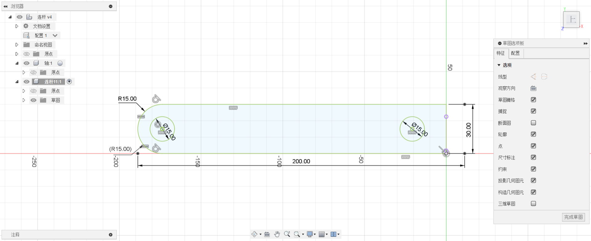
Apply Constraints
• Fix the Ground Link: Anchor the ground link using the Fix Constraint to prevent unintended movement.
• Apply Joints:
◦ Use Revolute Joints at pivot points (e.g., between crank and ground, crank and coupler, coupler and rocker).
◦ Ensure all joints are fully constrained to simulate realistic motion.
3D Modeling
• Extrude the Sketch: Use the Extrude tool to convert 2D sketches into 3D solid bodies. Assign uniform thickness to all links for simplicity. • Add Fillets: Apply Fillet edges to reduce stress concentrations at joints.
Assembly and Motion Study
• Assemble Components: Position the crank, coupler, and rocker relative to the ground link using constraints.
• Run Motion Analysis:
◦ Activate the Motion Study workspace.
◦ Define rotational drivers (e.g., apply angular velocity to the crank).
◦ Simulate the linkage’s movement to verify smooth operation.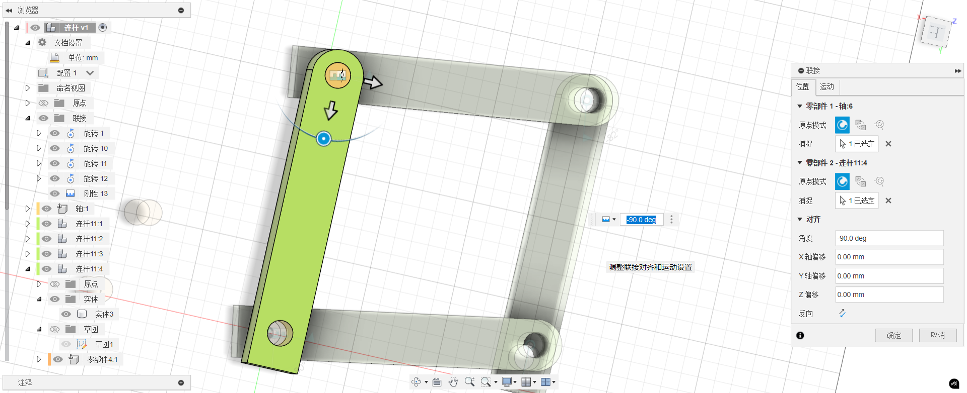
Key Tools Used:
• Sketch tools (Line, Dimension, Constraints).
• Extrude, Fillet.
• Joints and Motion Analysis.
3.Rhino
Rhinoceros, commonly known as Rhino, is a powerful 3D modeling software widely used in industrial design, architecture, jewelry, engineering, animation, and manufacturing. Developed by Robert McNeel & Associates, Rhino is best known for its precise NURBS-based modeling capabilities. 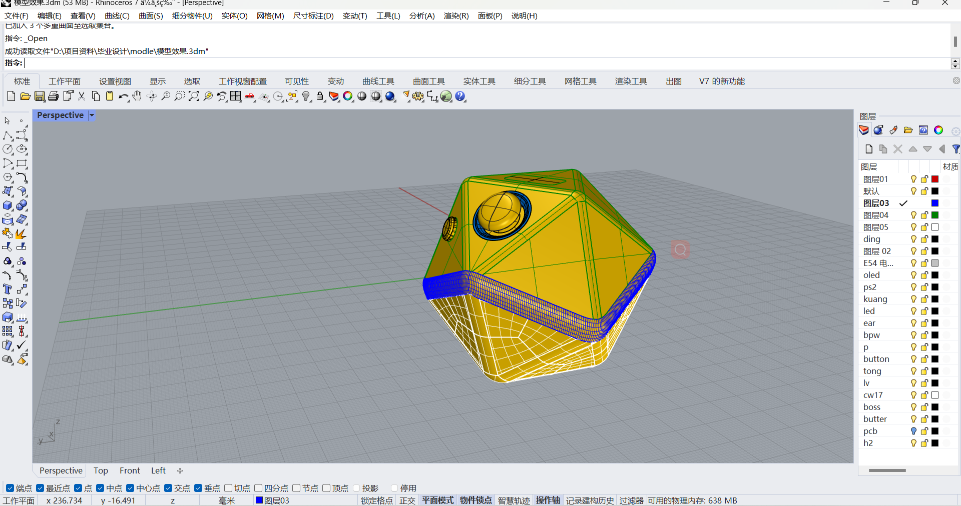
Key Features
- NURBS Modeling Engine: Enables accurate free-form surface modeling, ideal for complex geometries.
- High Compatibility: Supports a wide range of 3D file formats (e.g., DWG, STL, OBJ, IGES, STEP), making it easy to integrate with other CAD tools.
- Rich Plugin Ecosystem: Extensions like Grasshopper, V-Ray, KeyShot, and PanelingTools greatly enhance functionality.
- Lightweight & Efficient: Runs smoothly on modest hardware, making it accessible for students and startups.
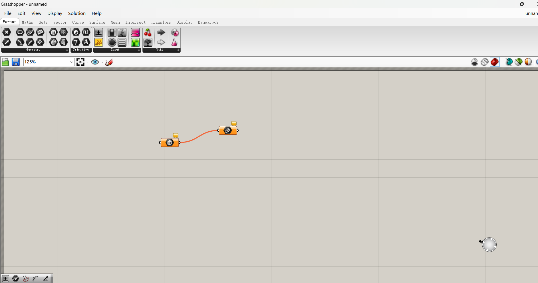
Grasshopper – Visual Programming for Parametric Design
One of Rhino’s most distinctive features is Grasshopper, a node-based visual programming tool for parametric modeling. Users can create complex logic-driven models without writing code by connecting visual components. Ideal for:
- Parametric architectural design
- Mathematical and algorithmic modeling
- Data-driven design
- Simulation and visualization workflows
Application Areas
- Architecture: Complex structures, façade systems, parametric urban planning
- Product & Industrial Design: Furniture, electronics, vehicle prototyping
- Jewelry Design: Precision surface modeling and rapid prototyping
- Engineering & Manufacturing: Export-ready models for CNC or 3D printing
Integration with Other Software
Rhino works seamlessly with many other tools, including:
- AutoCAD: Sharing 2D drawings via DWG format
- Revit: BIM integration through Rhino.Inside.Revit
- Blender / Maya / 3ds Max: Importing surface models for animation and rendering
- Unity / Unreal Engine: Real-time visualization and interaction design
4.Homework
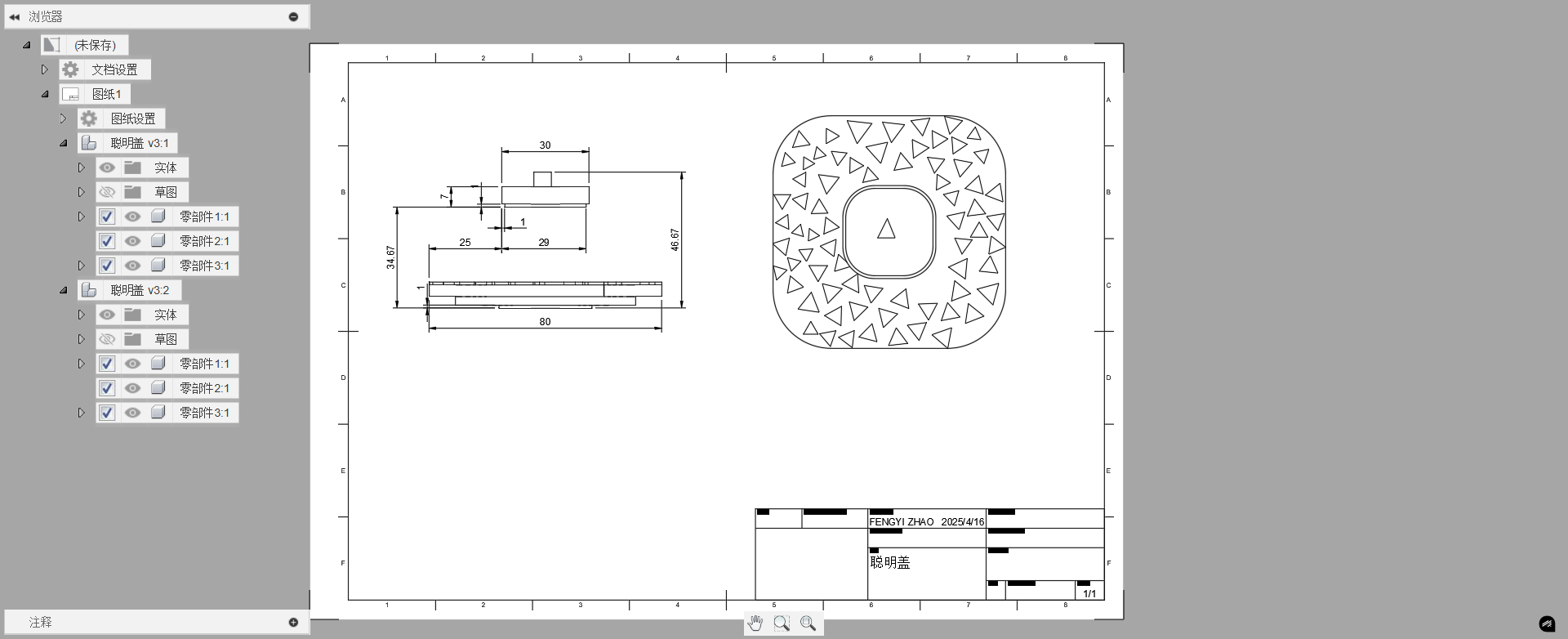
Model a functional aromatherapy bottle lid in Fusion 360*, then validate the design through 3D printing.
This is a special type of scented candle lid. By combining two LIDS, it achieves three functions: heat concentration, candle extinguishing and dust prevention.
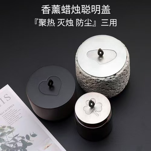
The female cover can gather heat and prevent the candle from burning out pits.
Modeling Workflow
Base Profile Sketch
Rounded Rectangle Sketch
• Create a 2D Sketch on the XY plane
• Use Center Rectangle tool (80x80mm) → Fillet edges (20mm radius)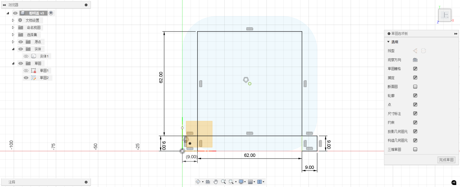 •
• Extrude 4mm with 1° draft angle for mold release
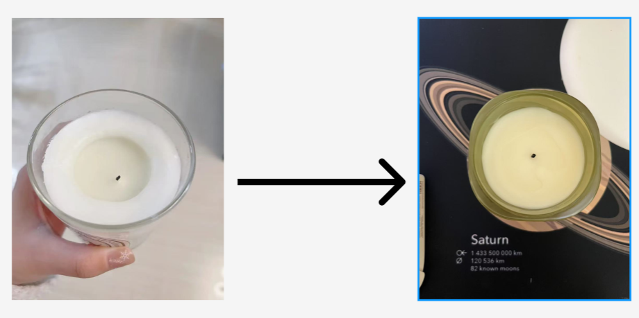
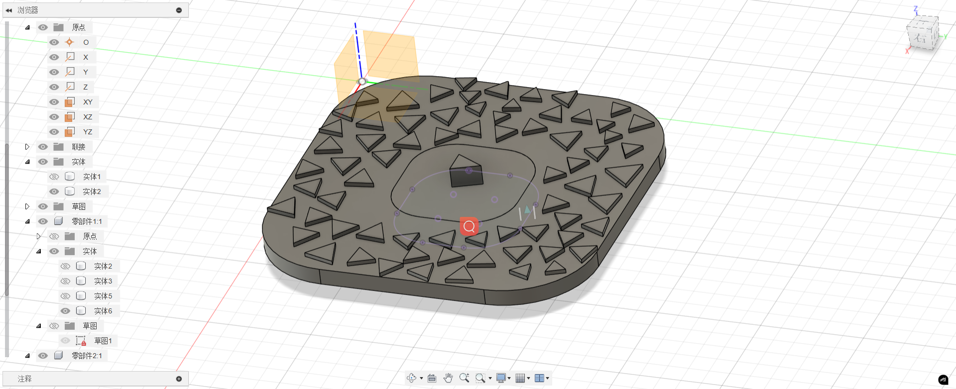
Creating Triangular Voronoi Patterns in Fusion 360
Base Geometry Setup
• Create a new sketch on the desired plane (e.g., XY, XZ, or YZ).
• Draw boundary geometry (e.g., rectangle, circle, or custom shape) to define the pattern area.
Voronoi Pattern Generation
• Open the Voronoi Sketch Generator from the Add-Ins menu.
• Select all seed points as input geometry.
• Set parameters:
• Pattern Type: Triangular Tessellation
• Border Offset: 0mm (for full coverage)
• Click Generate to create the Voronoi cells.
3D Application
• Extrude (0.5–2mm) for engraved surface details.
Add the child cover and female cover to the coupling • The picture shows how the two LIDS are moved and assembled. 
Engineering drawing model