Appearance
CAD
1. Fusion 360 Introduction
Fusion 360 is a cloud-based CAD/CAM/CAE tool for collaborative product development. Fusion 360 combines fast and easy organic modeling with precise solid modeling, allowing you to make your designs manufacturable. Last but not least,With the help of Eagle,Fusion has the function of Electromechanical.
1. Creat sketch
Firstly, creat a new part.
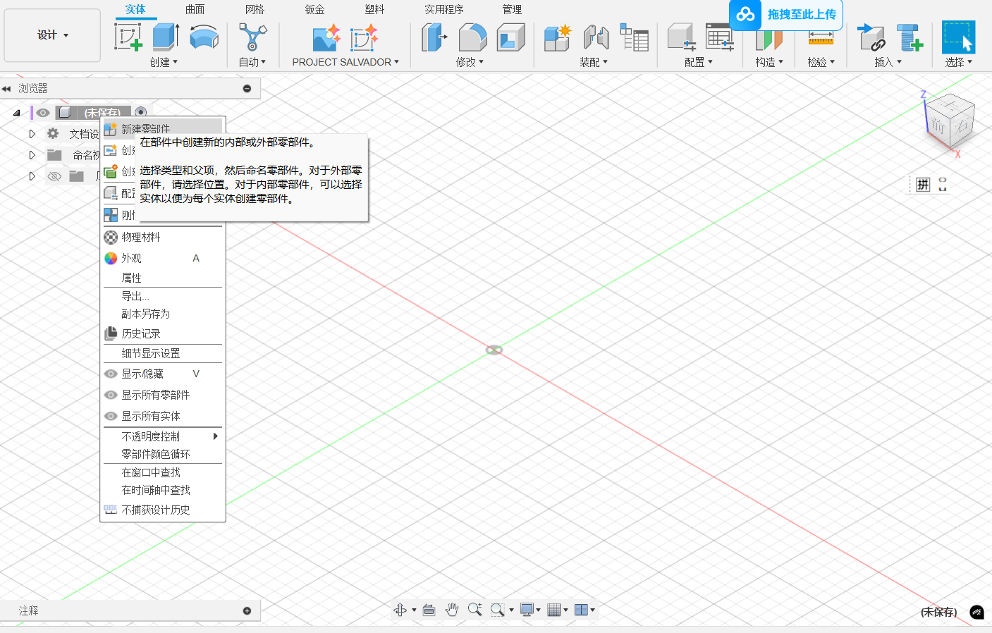
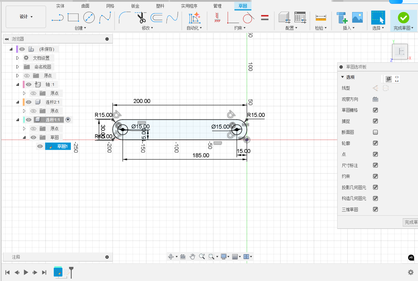
Choose a panel to sketch a retangle.

To define the sketch compeletly, some sizes are needed to ensure,such as the angle, length etc. In addition, the place of the sketch should be defined, whcih is the length between sketch and origin point.
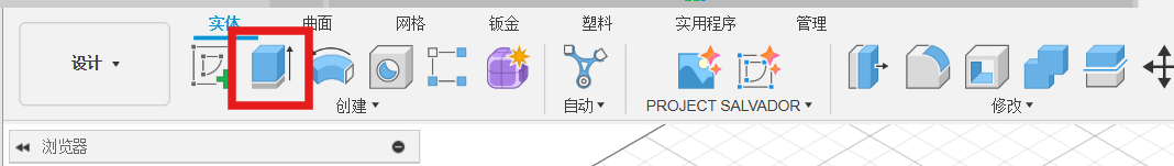
2. Creat part
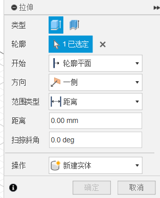
To convert the sketch into a part, we will use stretch tool to pull the sketch along a direction. The thickness is defined in this process.
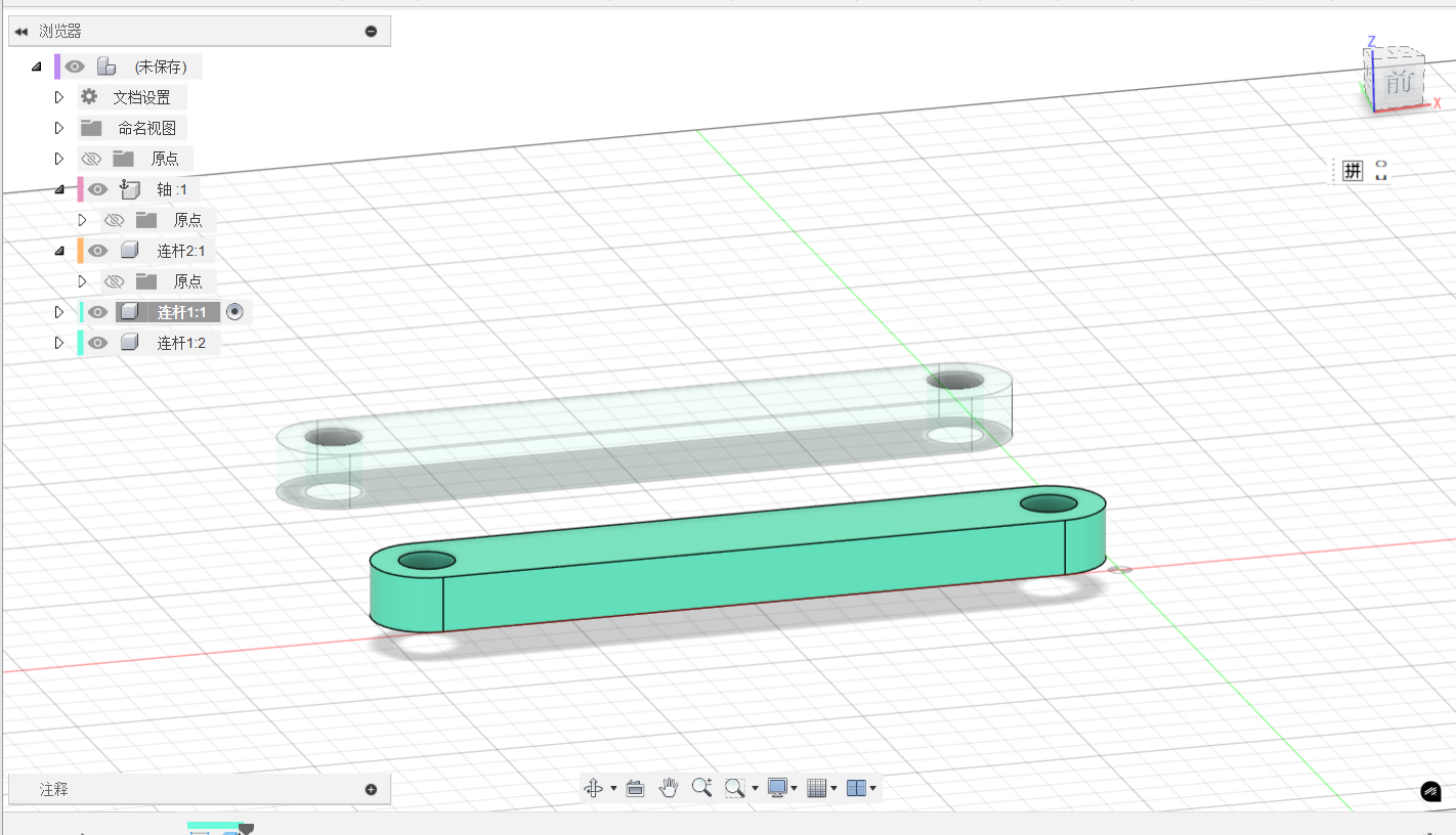
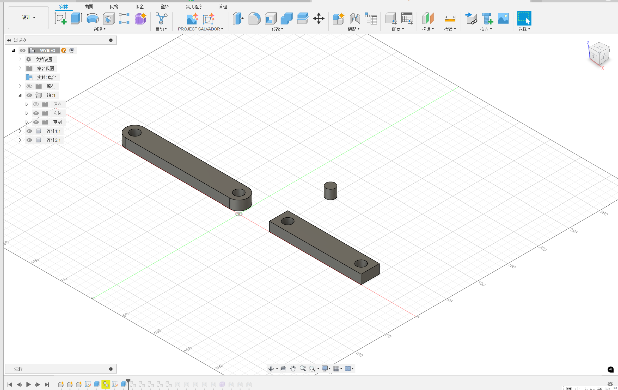
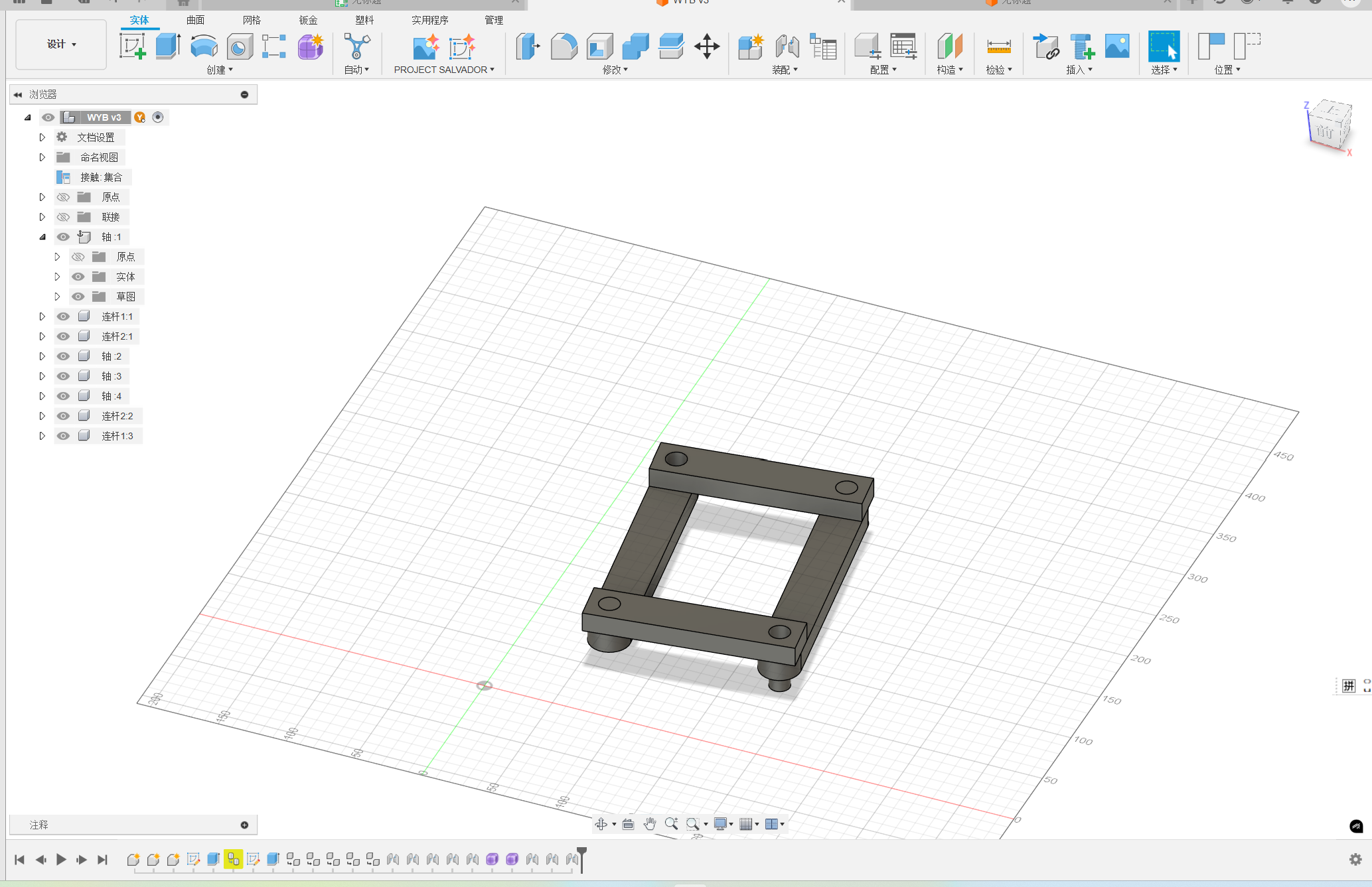
3. Add more parts
You can add more parts to the model by using the same method. In addition, you can use the copy and paste to add more parts.
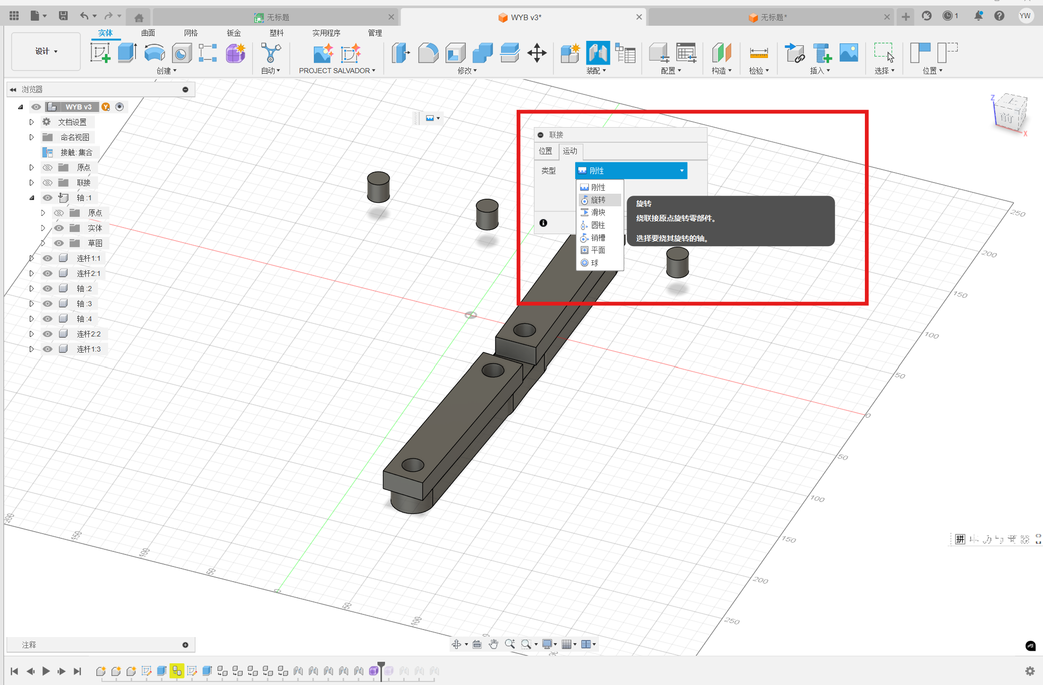
4. Cooperate the parts
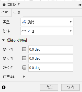
To assemble these parts, you can use the connection tool to make them cooperate. Choose the assemble type firtly. In the step, you can let the part rotate or attched to the another part.
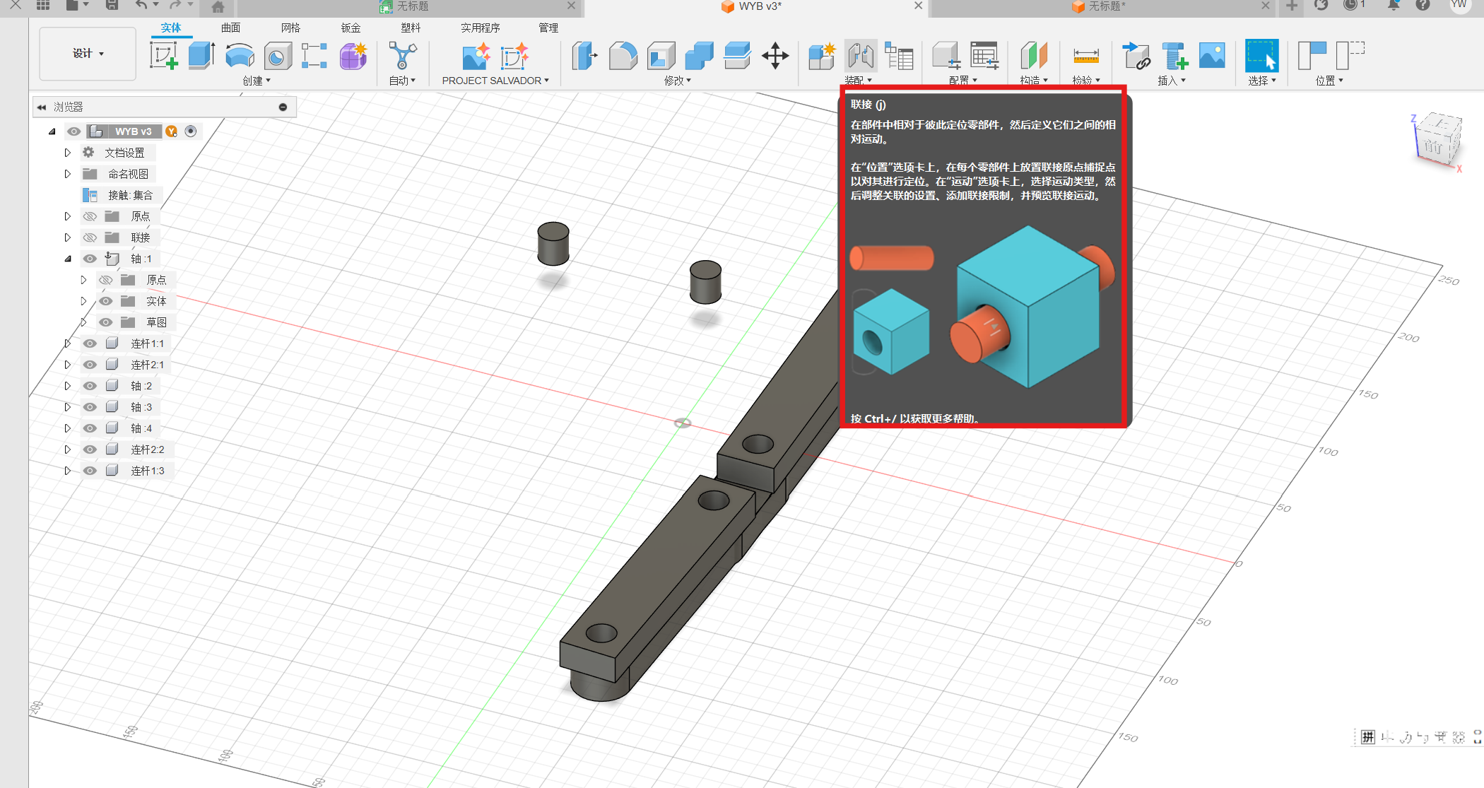
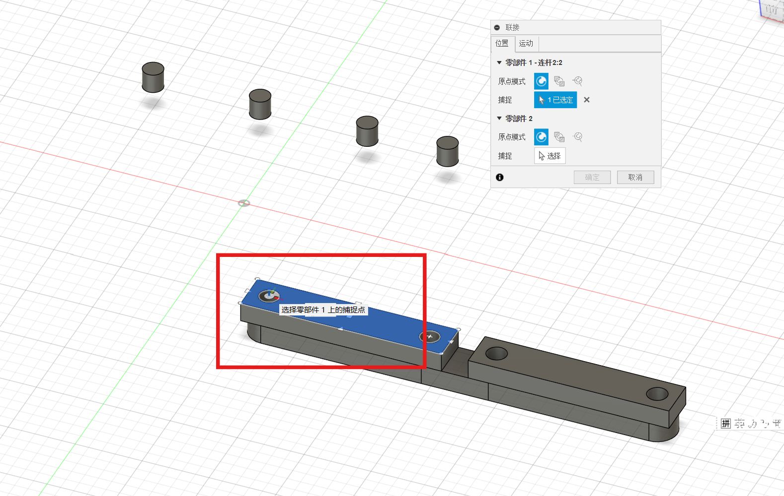
Then, choose the connection surface or point to another part, the two parts can be connected automaticly.
2. Fusion 360 Automated modeling
Automated Modeling is a new tool in the Design Workspace that automates the process of exploring and creating new design concepts based on simple definitions of what to connect and what to avoid. You can find the Automated Modeling tour here.
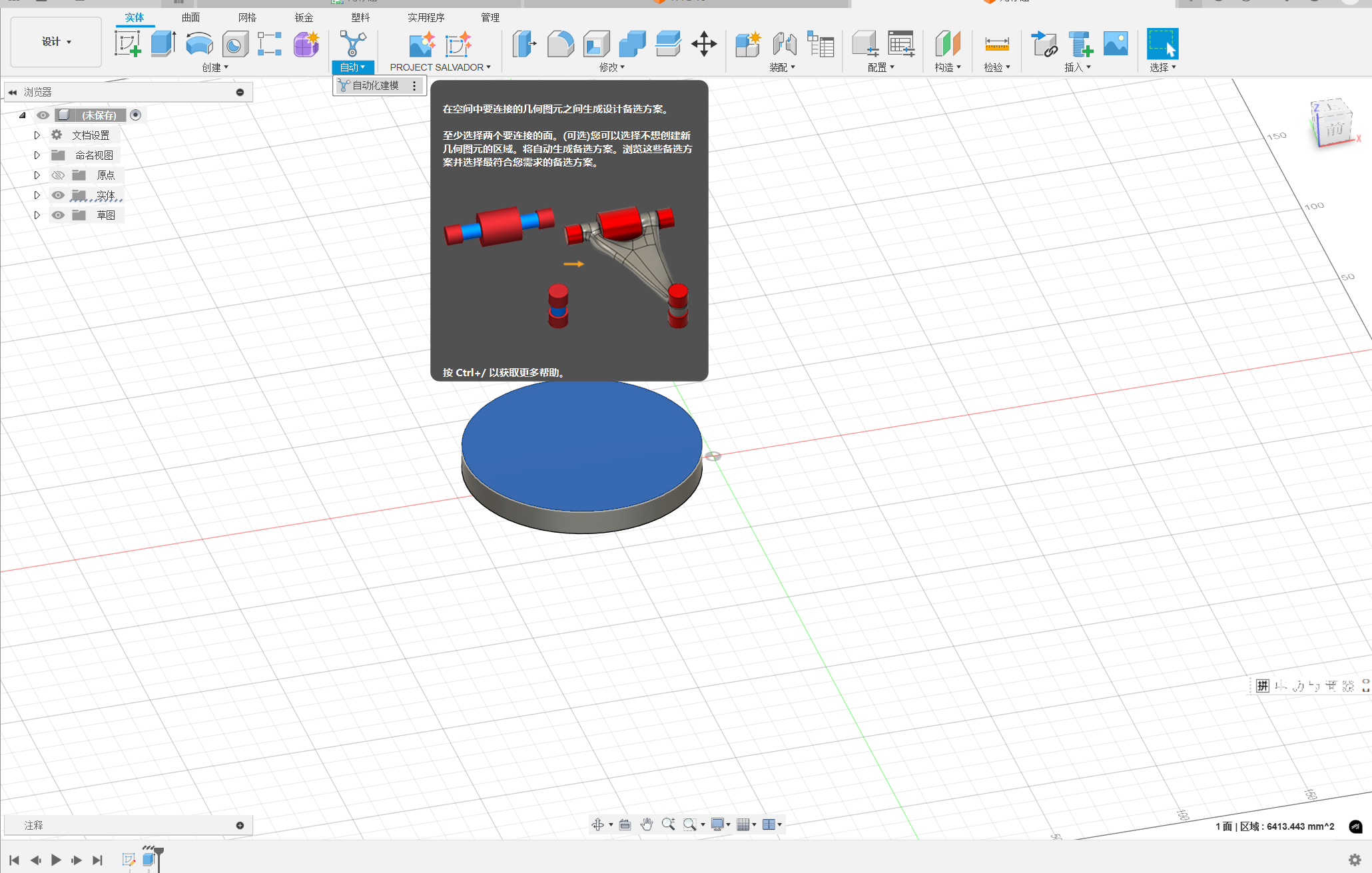
To creat the solution, you will need to define Faces to Connect and, optionally, Bodies to Avoid. Then the solution will be generated.
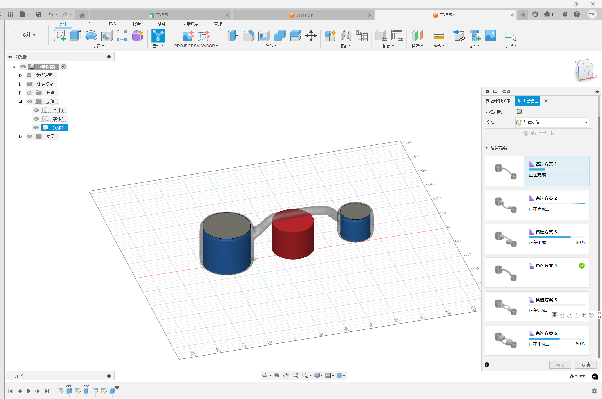
You can adjust the paramters of the solution to ensure the generate effect.
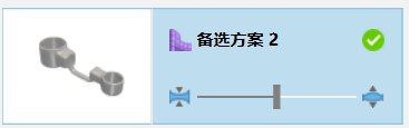
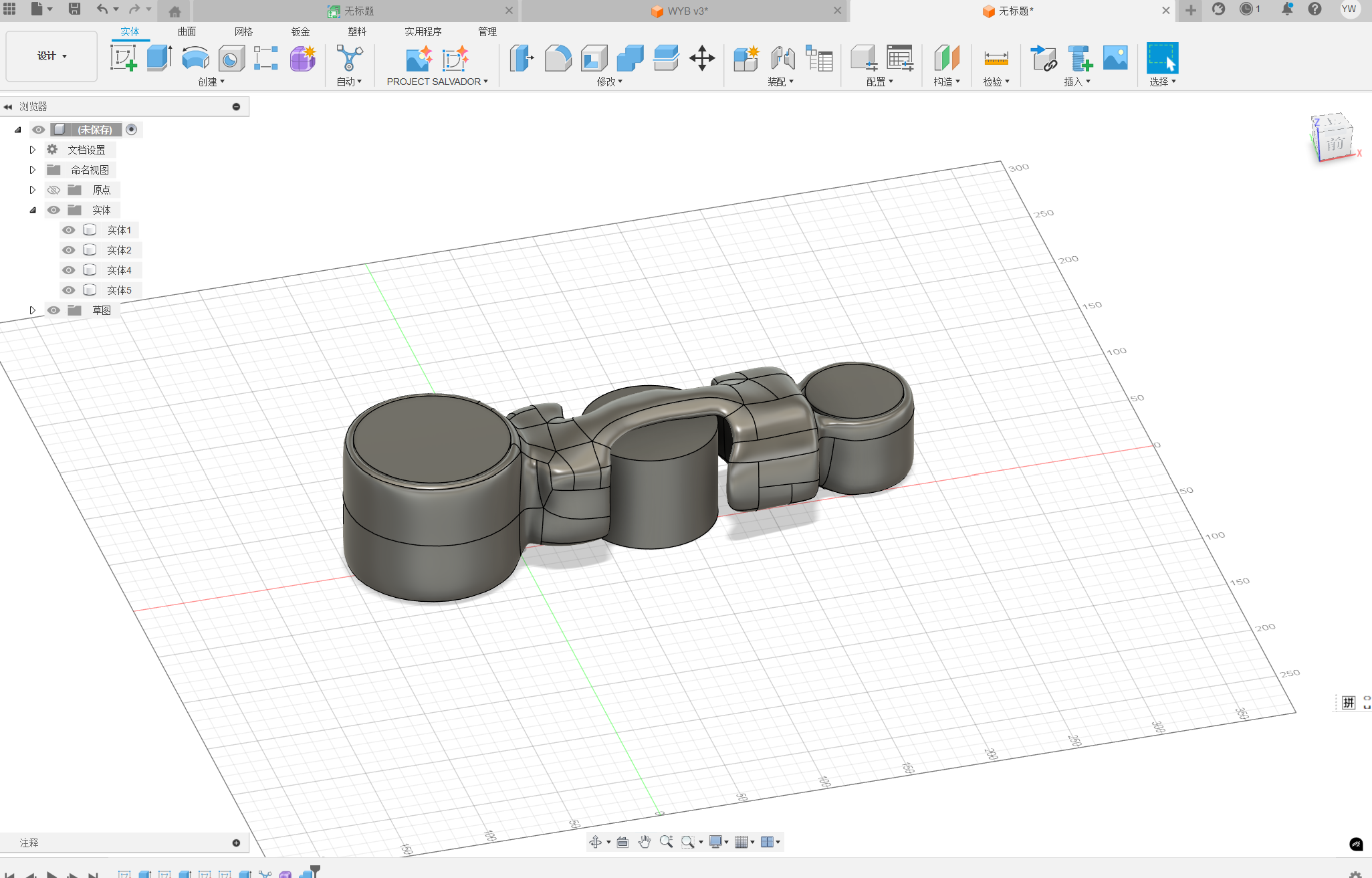
Then, you can use the solution to generate the model.
3. Fusion 360 Plugin practice
In this part, we will practice two plugins.
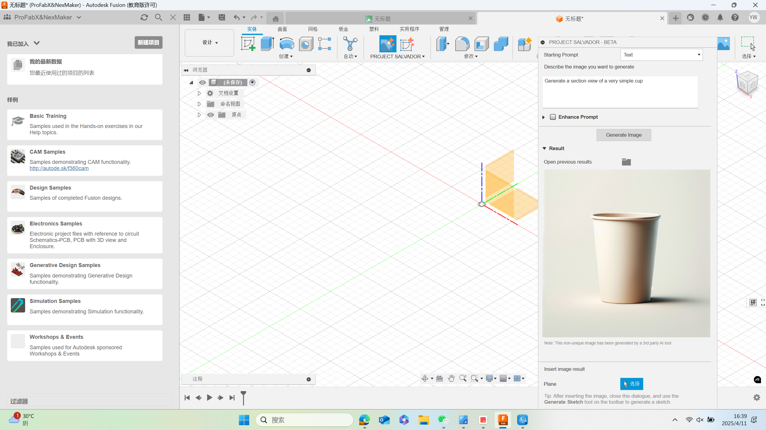
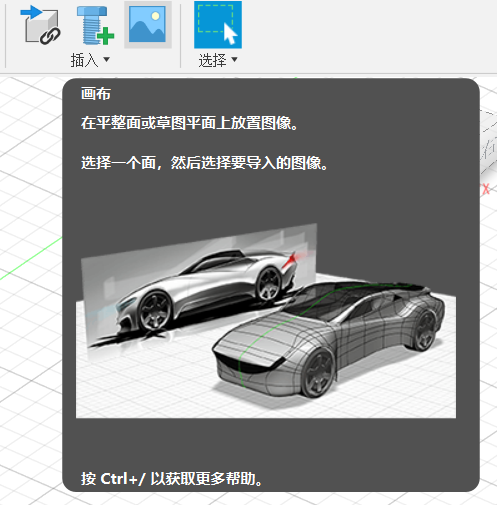
Project salvador is an Autodesk Fusion add-in that provides access to third-party Generative AI models through the APIs1. It allows users to create AI-generated images inside Fusion and automatically generate sketches2. Another add-in generates Voronoi diagrams, which can be inserted into a sketch and used for creating or modifying models3.
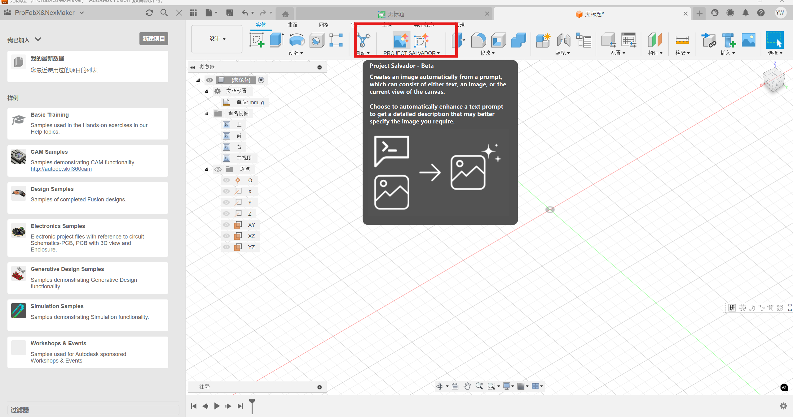
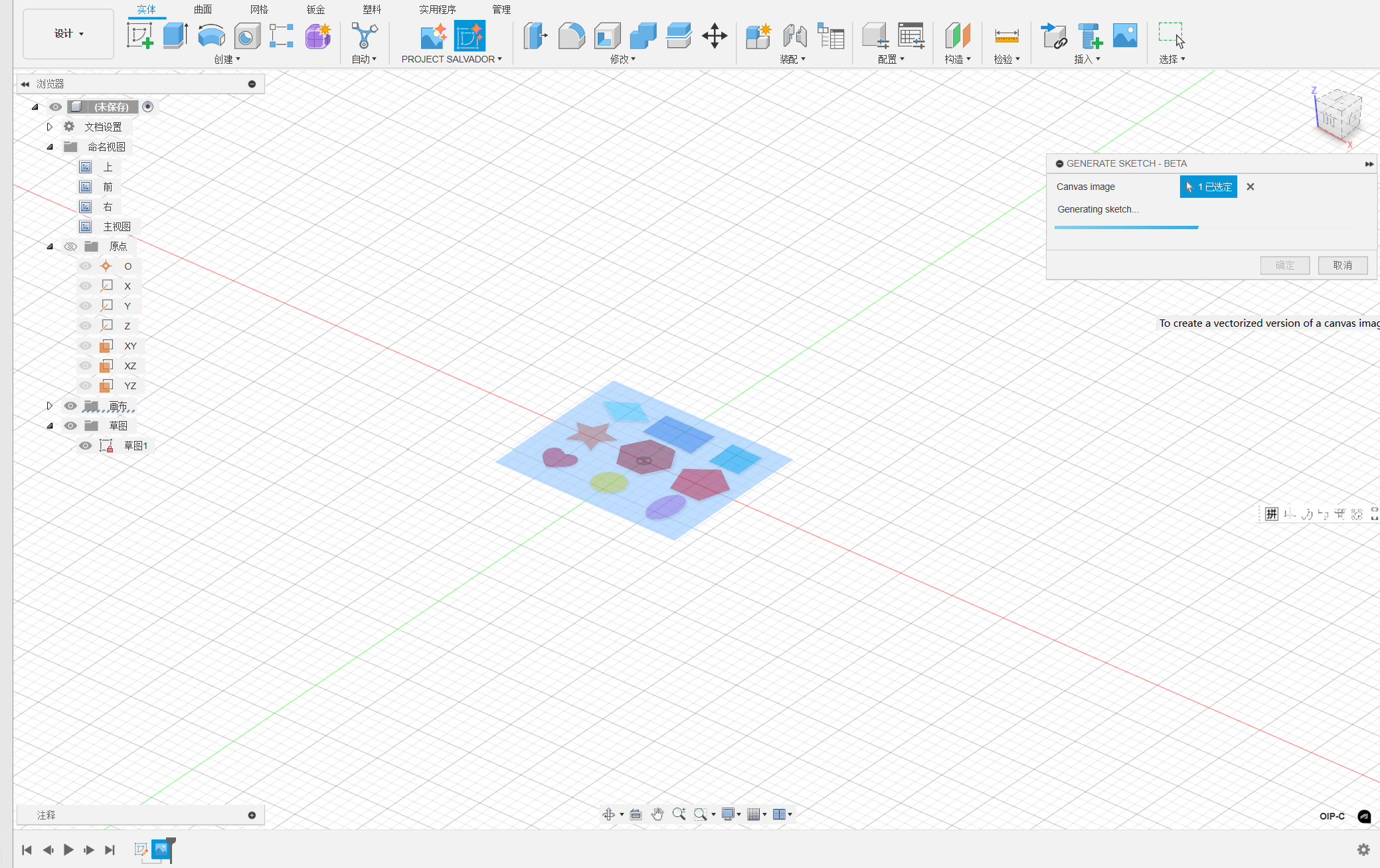
Firstly, decribe the image you want to generate. Then, click generate the image.
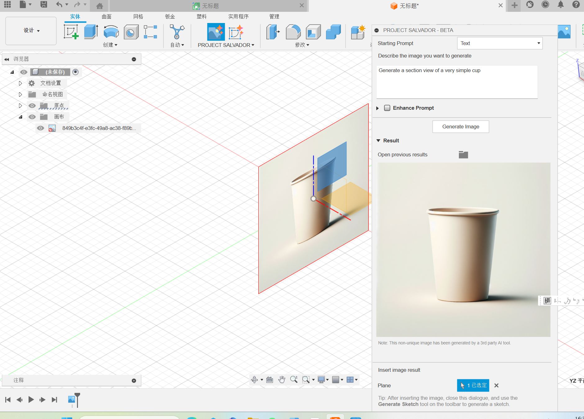
Choose e section plane for the image.
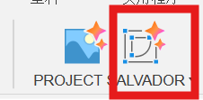
Then click the generate sketch button.
Choose the target image.
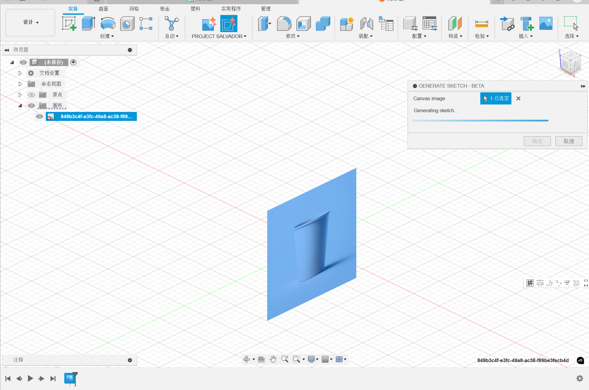
After converting the image into sketch. The rough sketch was generated. However, the effect is not well here, which might be caused to the undetailed description. In addirion, too complexed image might caused the failure.
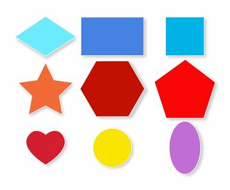
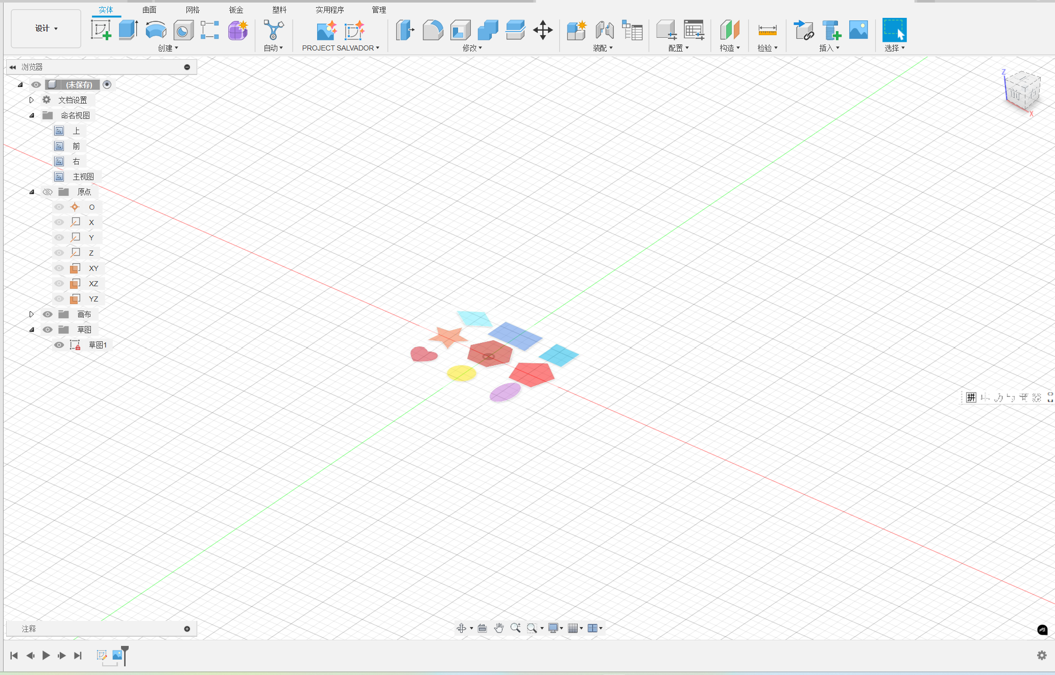
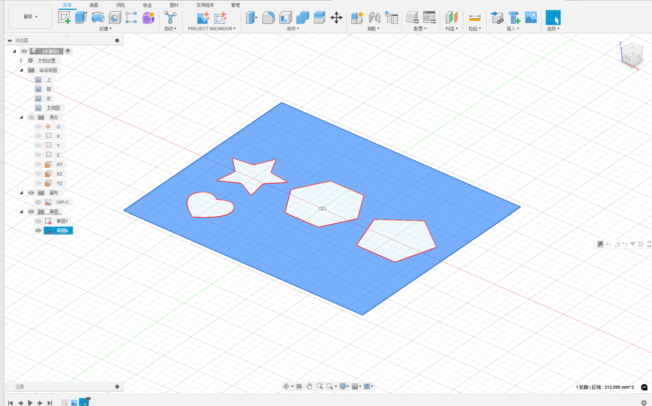
Thus, I choose a current simple 2D pattern image to generate the sketch by the plugin.
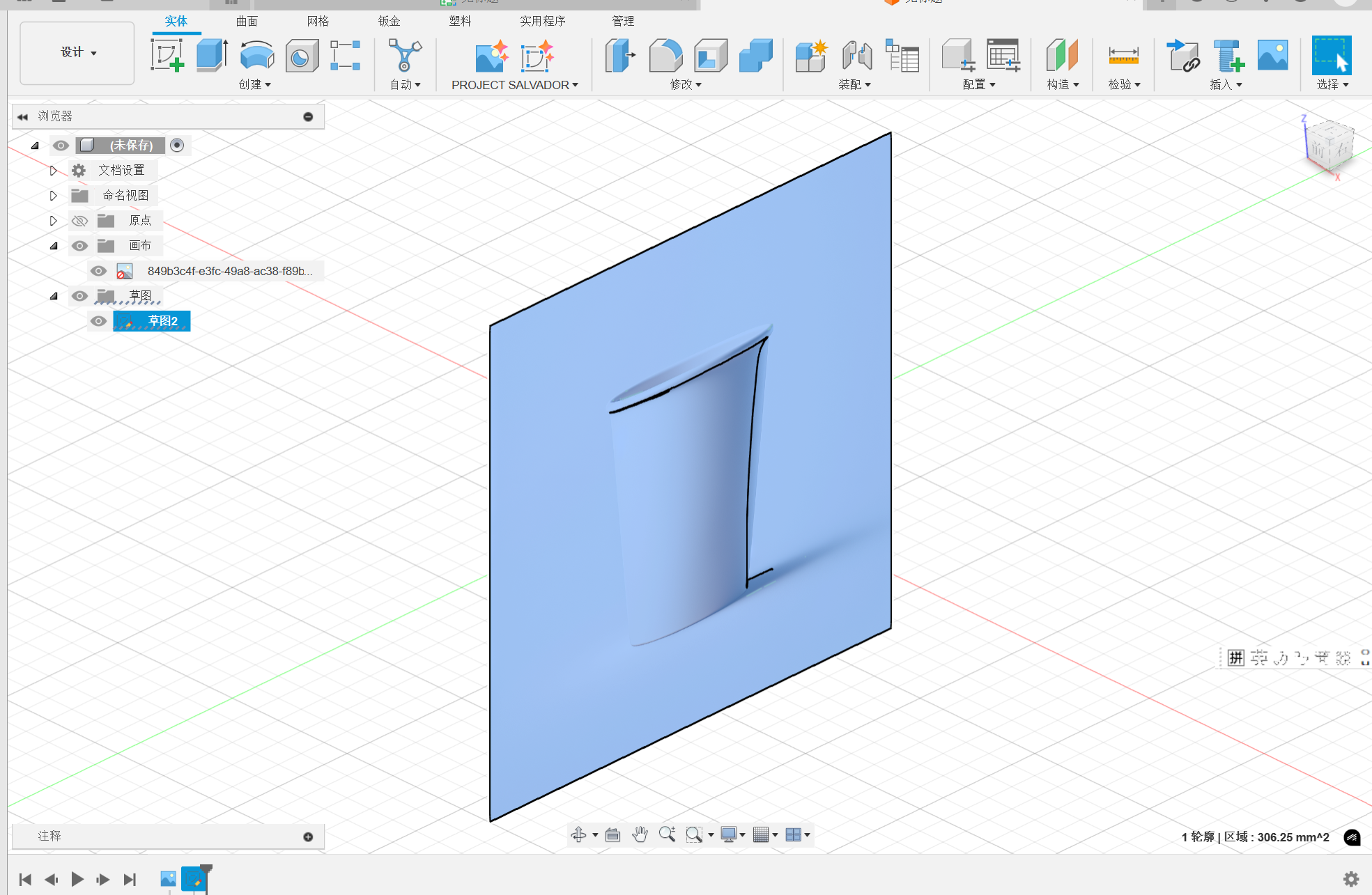
Then i pitch on the underside plane to paste the imgae.
After that, I use the plugin to generate a sketch according to the image.
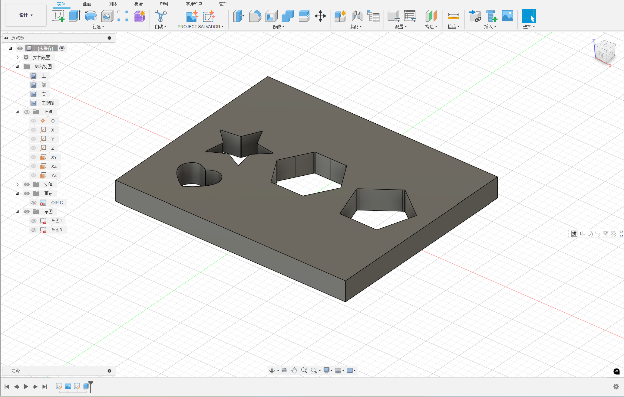
Then, the sketch was generated and you can creae the part freely.
4. Parameter class design practice
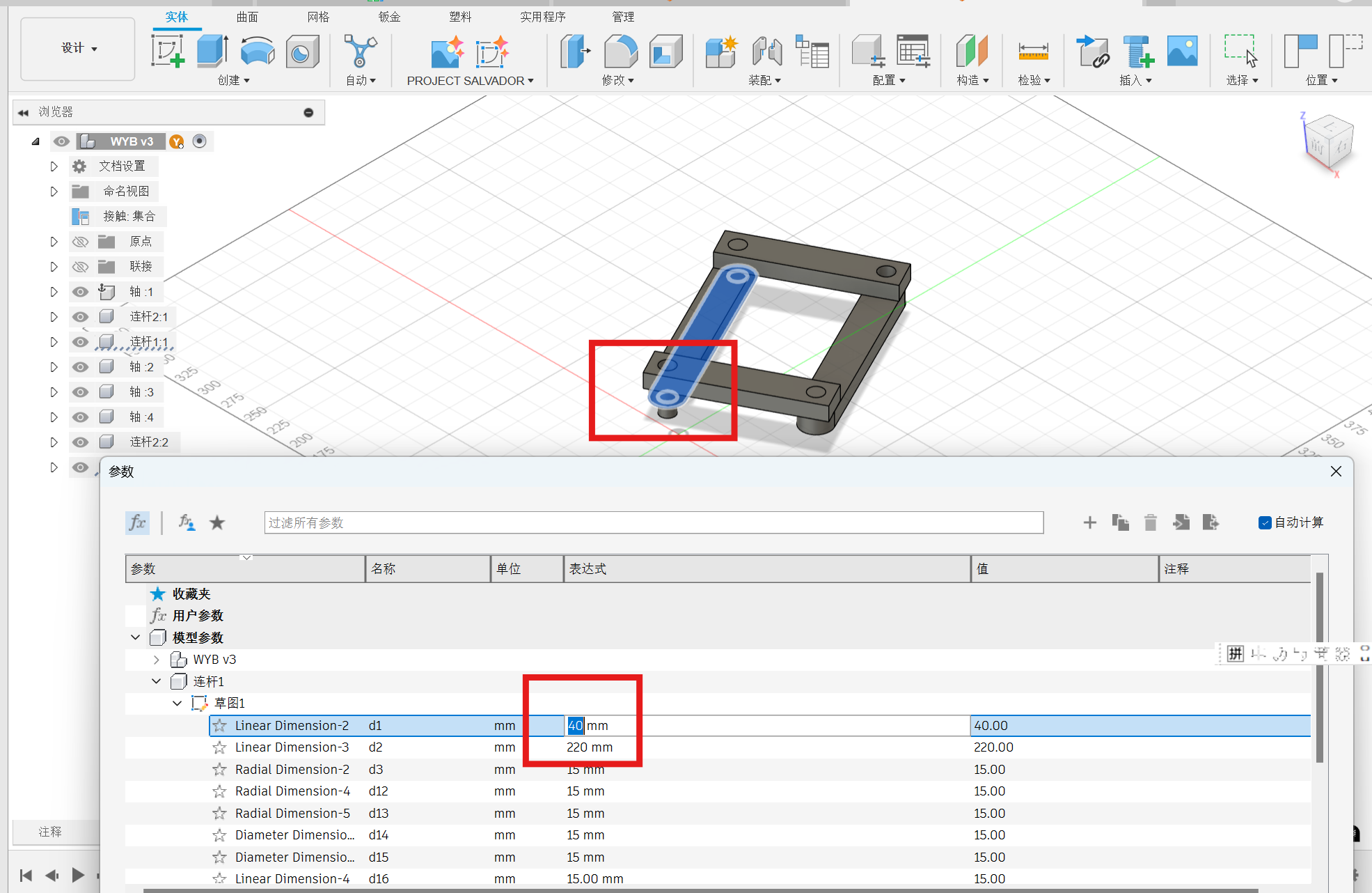
Parametric modeling is an approach to 3D CAD where you reach the design intent is by altering features and constraints. This allows designers to automate repetitive changes. Parametric modeling allows for creating mathematical relationships (modeling features) between sketches and the final model. These are stacked on each other over time and thus become intertwined. In other words, modifying the parameters of one feature will affect other features.
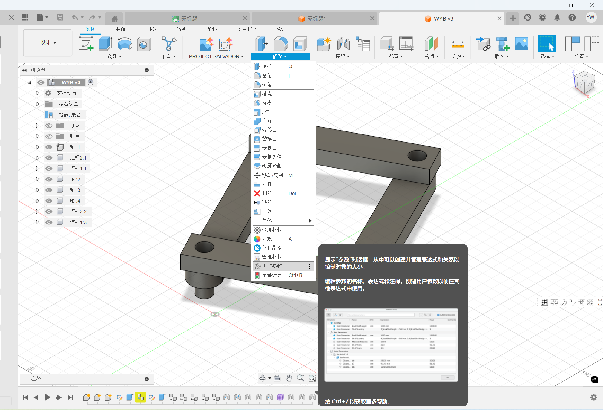
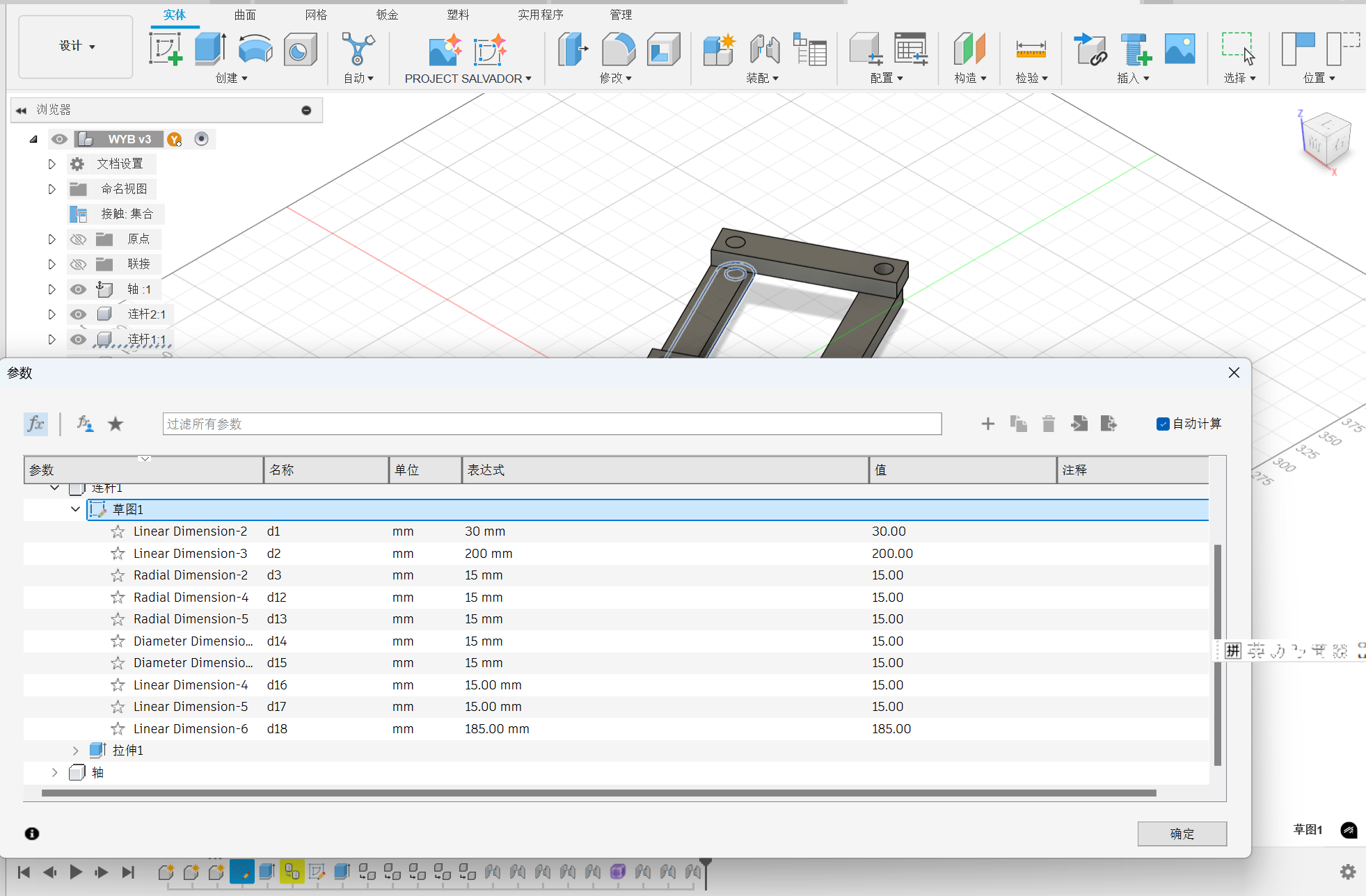
After changing the parameters, the model will be changed automatically. Add more dimensional constraints can make the modle scale more coordinated.
5. Fuison 360 design practice of universal coupling
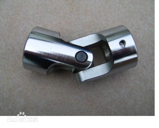
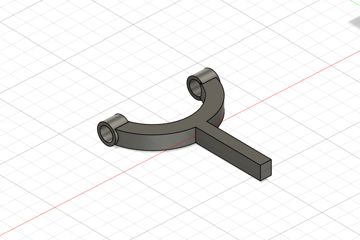
A universal joint is a joint that connects two levers, consisting of a pair of ordinary hinges with a relative orientation of 90°, which allows the lever to be steered in any direction, and is still widely used in vehicle transmissions.
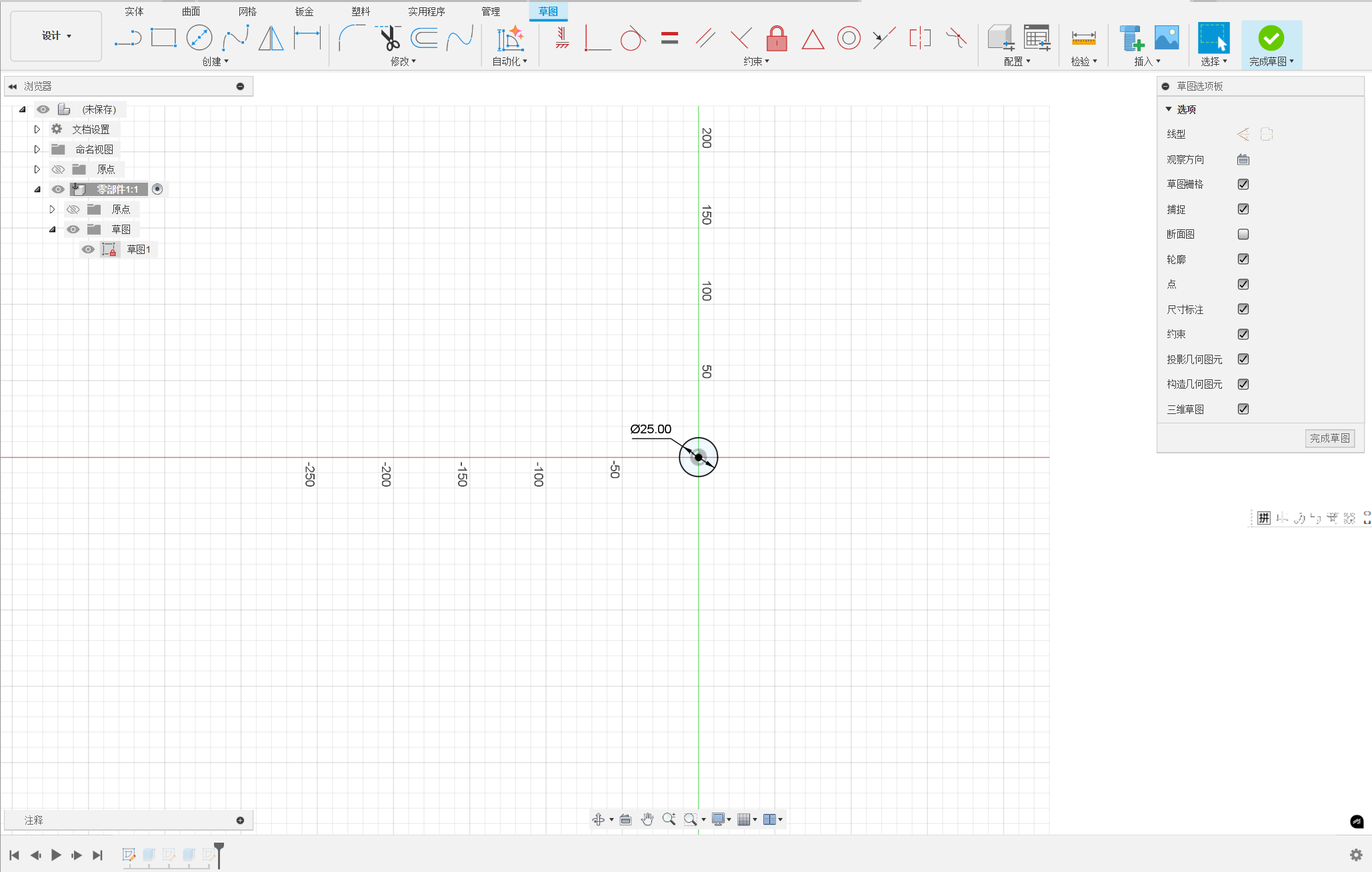
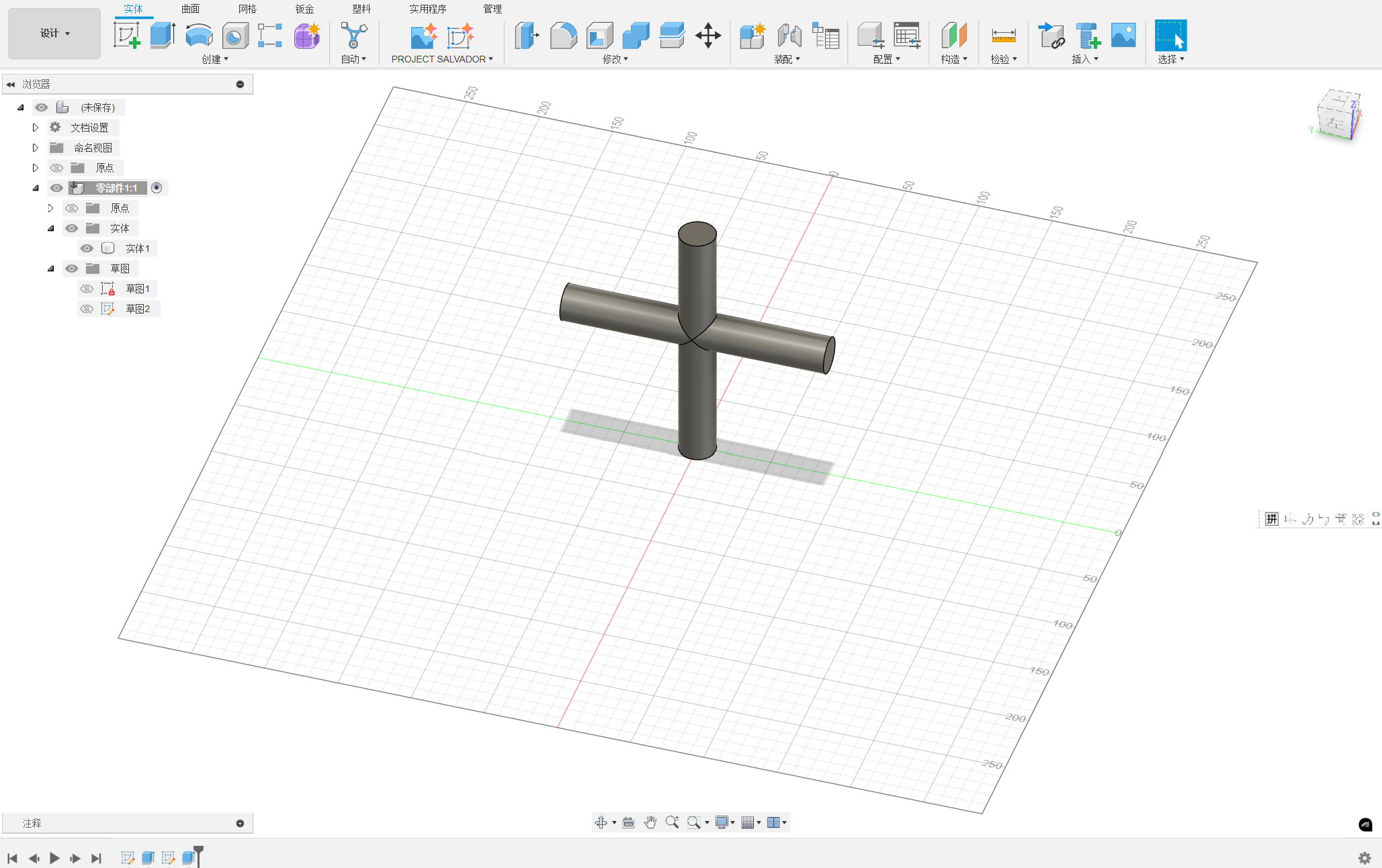
To creat the part, two axes perpendicular to each other are established. The diamater of the roller is 25mm.
Strtech the roller to the vertical axes and landscape axes with 190mm.
Then, establish the joint section.
Sketch the shape.
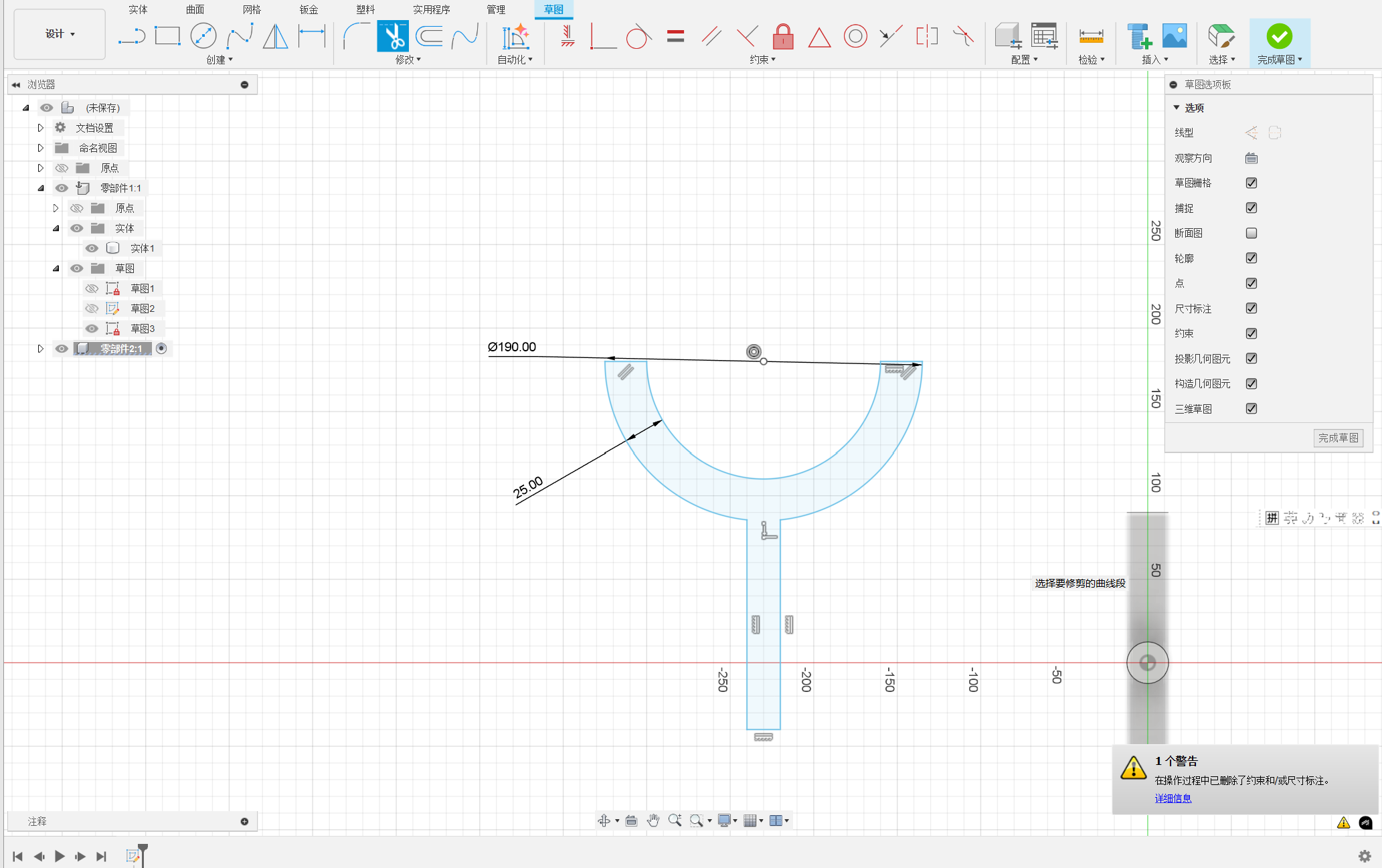
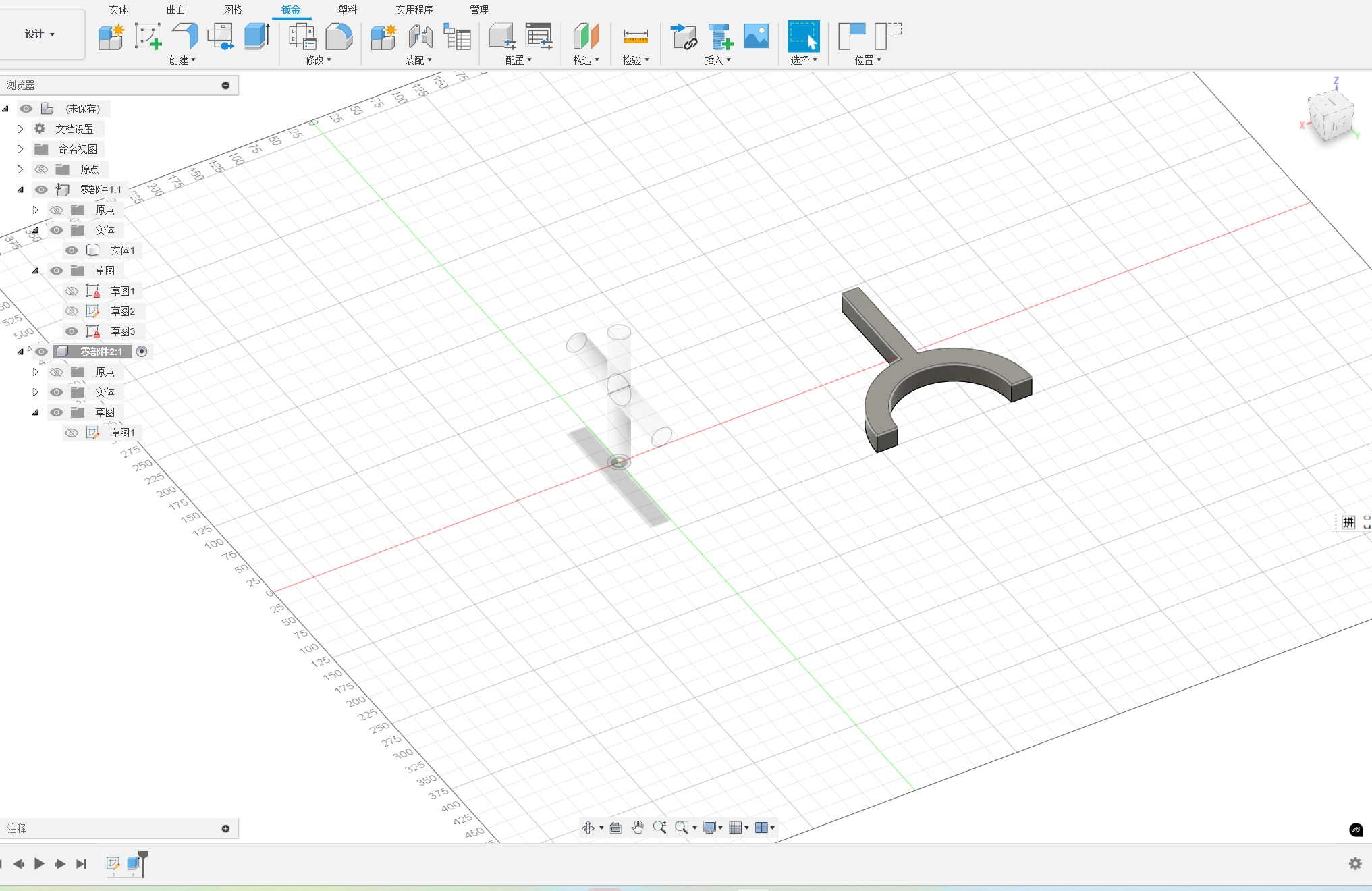
Stretch the sketch.
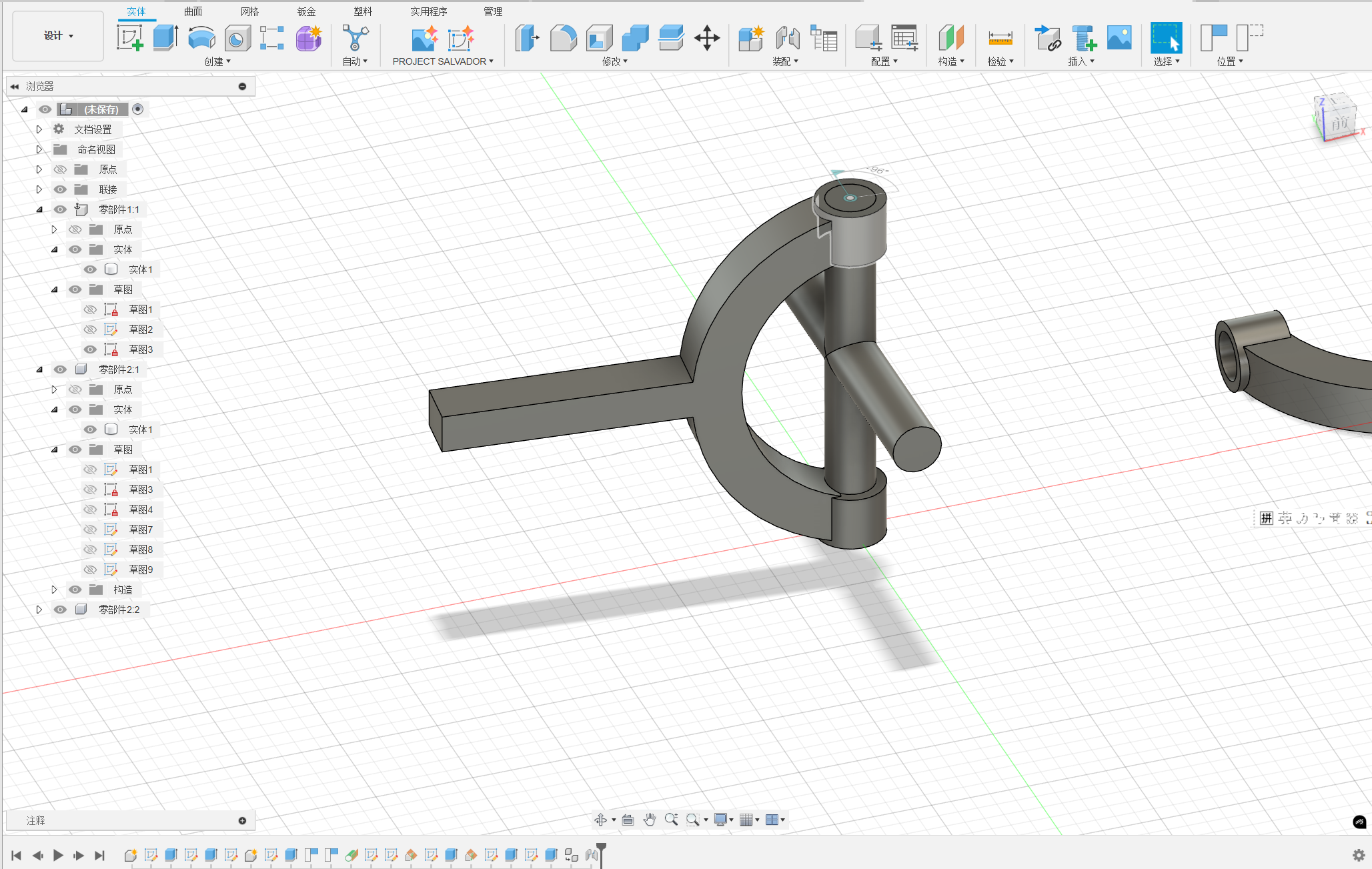
Establish a plane that is tangential to the joint.
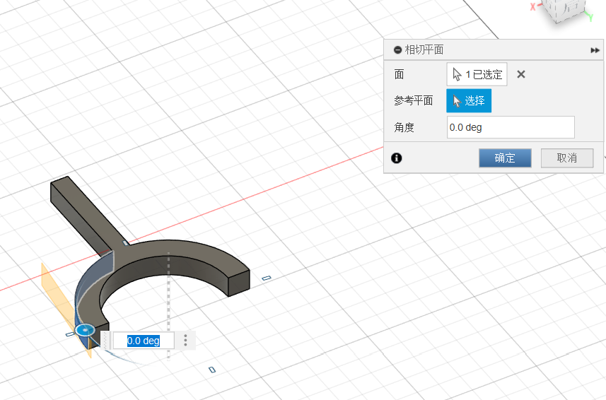
Creat the instert hole.
Copy the other joint.
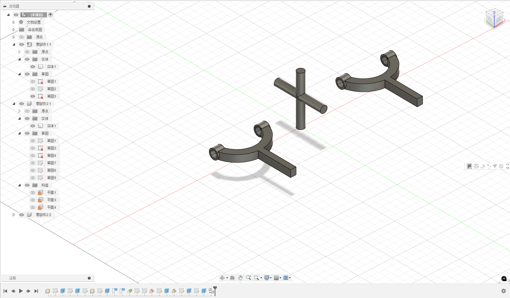
Then assemble the joint.
And the other joint.
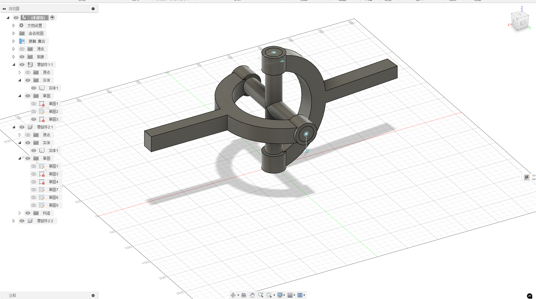
Finally, Start the contact collection.
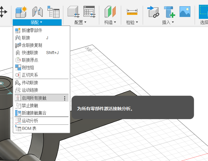
Creat new contact collection.
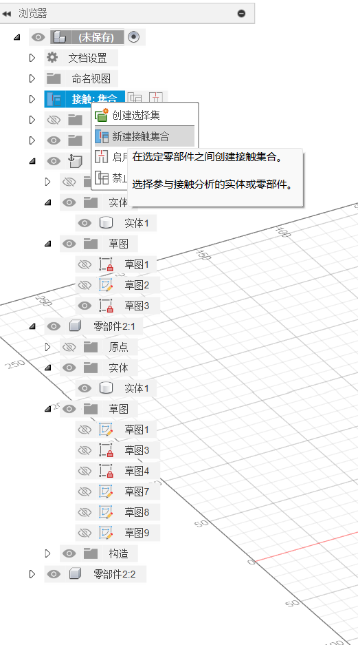
Select the two parts for contacy collection.
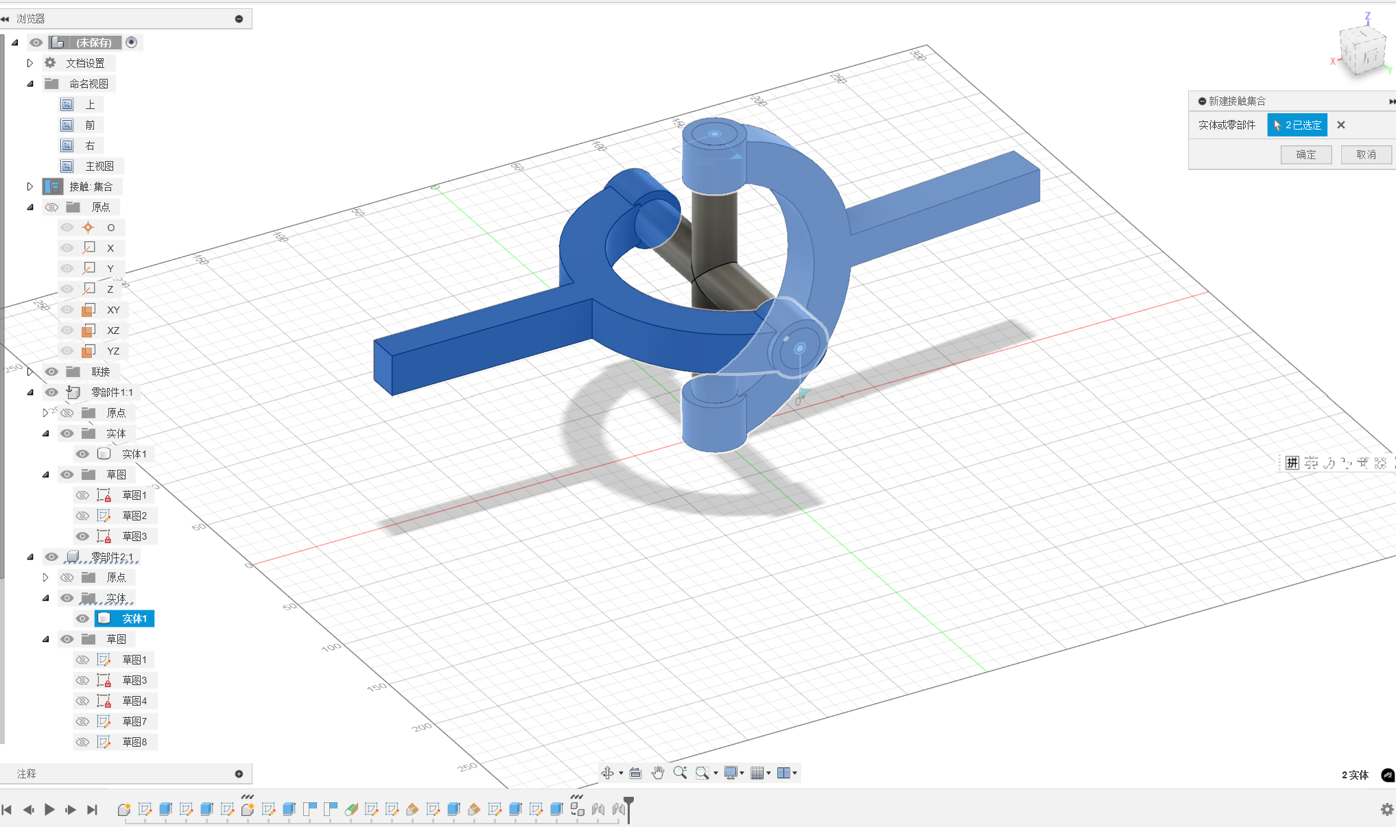
Let's preview the effect!
6. Solidworks introduction
SOLIDWORK 3D CAD is the choice for professionals around the world who need to take design innovation further, produce products faster, and reach the highest levels of efficiency in their day-to-day product development work. Decades of user-driven enhancements and a relentless R&D focus on user experience has made SOLIDWORKS 3D CAD not just powerful, but both easy to learn and fun to use. In addition, solidworks also can rendering the product easily. Click here to download the solidworks. More information about solidworks can be find in https://www.solidworks.com/product/solidworks-3d-cad