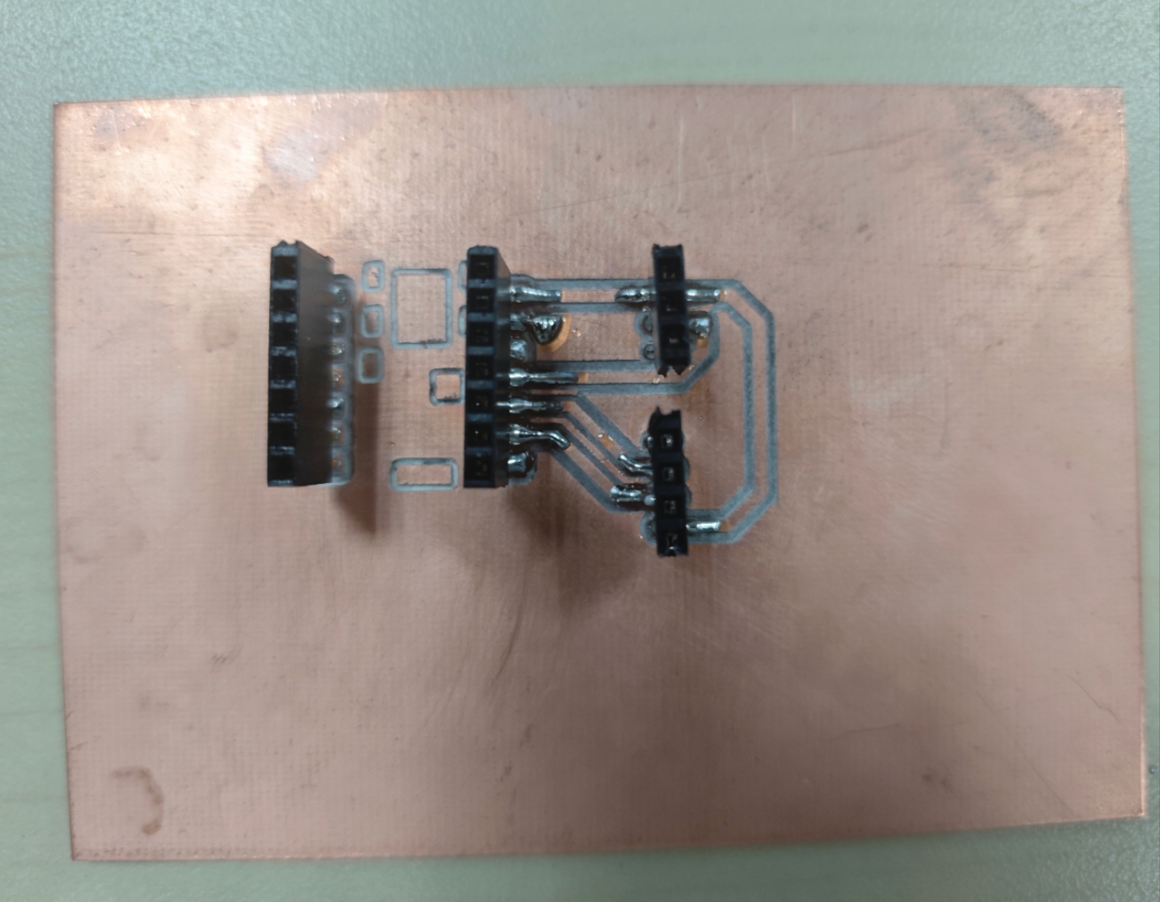
Appearance
PCB Production
1. CNC
CNC technology refers to the use of computers to control machine tools. The machine follows a set of instructions from a computer program, often written in G-code or similar languages, to perform tasks like cutting, drilling, milling, or turning materials with high precision. CNC technology has significantly enhanced productivity, precision, and flexibility in manufacturing processes.
1. Turning Turning is a machining process where a cutting tool is used to remove material from a rotating workpiece. The workpiece is mounted on a spindle and rotated while the tool moves along the length of the piece to shape it.
2. Drilling Drilling is a process used to create round holes in a workpiece using a rotating cutting tool, typically a drill bit. In CNC drilling, the tool’s movements are controlled by a computer program that directs the machine to the precise location and depth of the hole.
3. Grinding Grinding is a finishing process that uses an abrasive wheel or belt to remove material from a workpiece, creating a smooth and refined surface. CNC grinding machines automate this process, ensuring accurate control of grinding wheel movements for highly precise finishes.
2. CNC Manuacture
1. CNC Drilling in PCB Manufacturing:
Drilling is one of the most critical processes in PCB production. PCBs require numerous holes (called vias) for electrical connections between layers, as well as holes for mounting components.
Process:
A CNC drilling machine uses a rotating drill bit controlled by a computer to precisely drill small holes at specific locations on the PCB. The depth and diameter of the hole are also controlled via the CNC program.
Holes can vary in size from small via holes (for connecting layers) to larger component holes (for mounting components like resistors, capacitors, and connectors).
Benefits:
Precision: CNC drills ensure that the holes are placed with high accuracy, even for multi-layer PCBs.
Efficiency: CNC machines can drill thousands of holes in a very short amount of time, making them essential for high-volume production.
Reduced Error: CNC automation eliminates human errors in hole placement, which is crucial in maintaining the electrical performance of the PCB.
2. Design simple PCB with Fusion360:
1. PCB schematic diagram
Using Fusion 360 to design a simple PCB schematic diagram. Firstly, select the suitable electric compoments into the plate.
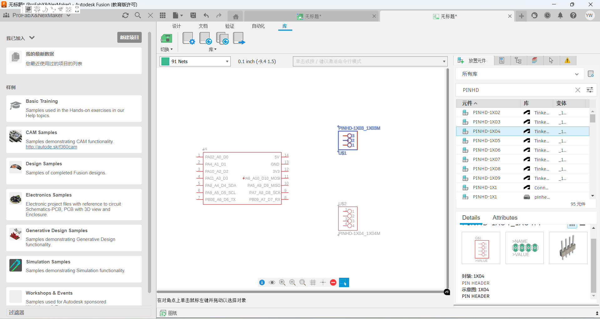
Then, connecting the electric compoments with wires.
After that, convert the disgram into PCB.
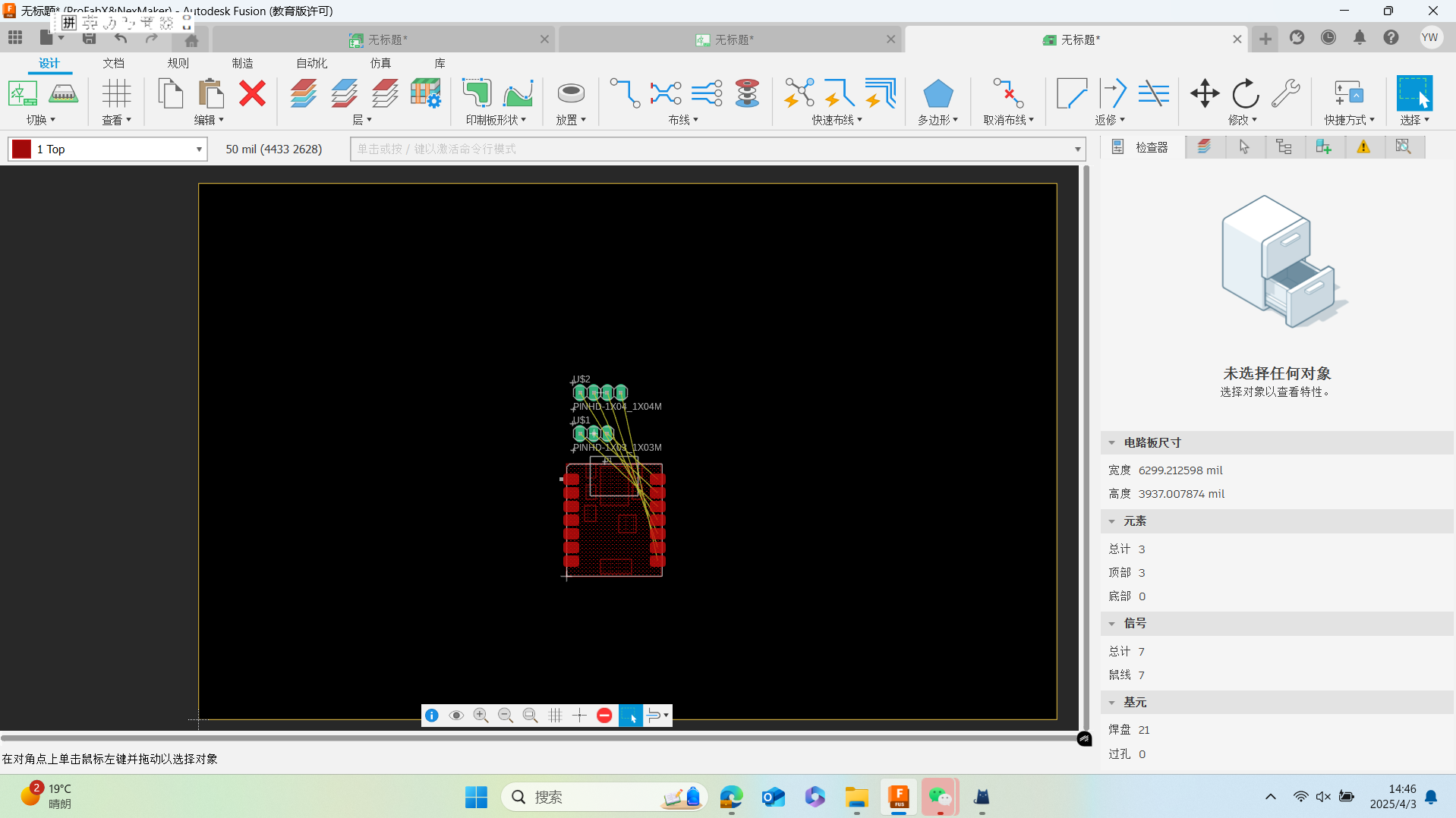
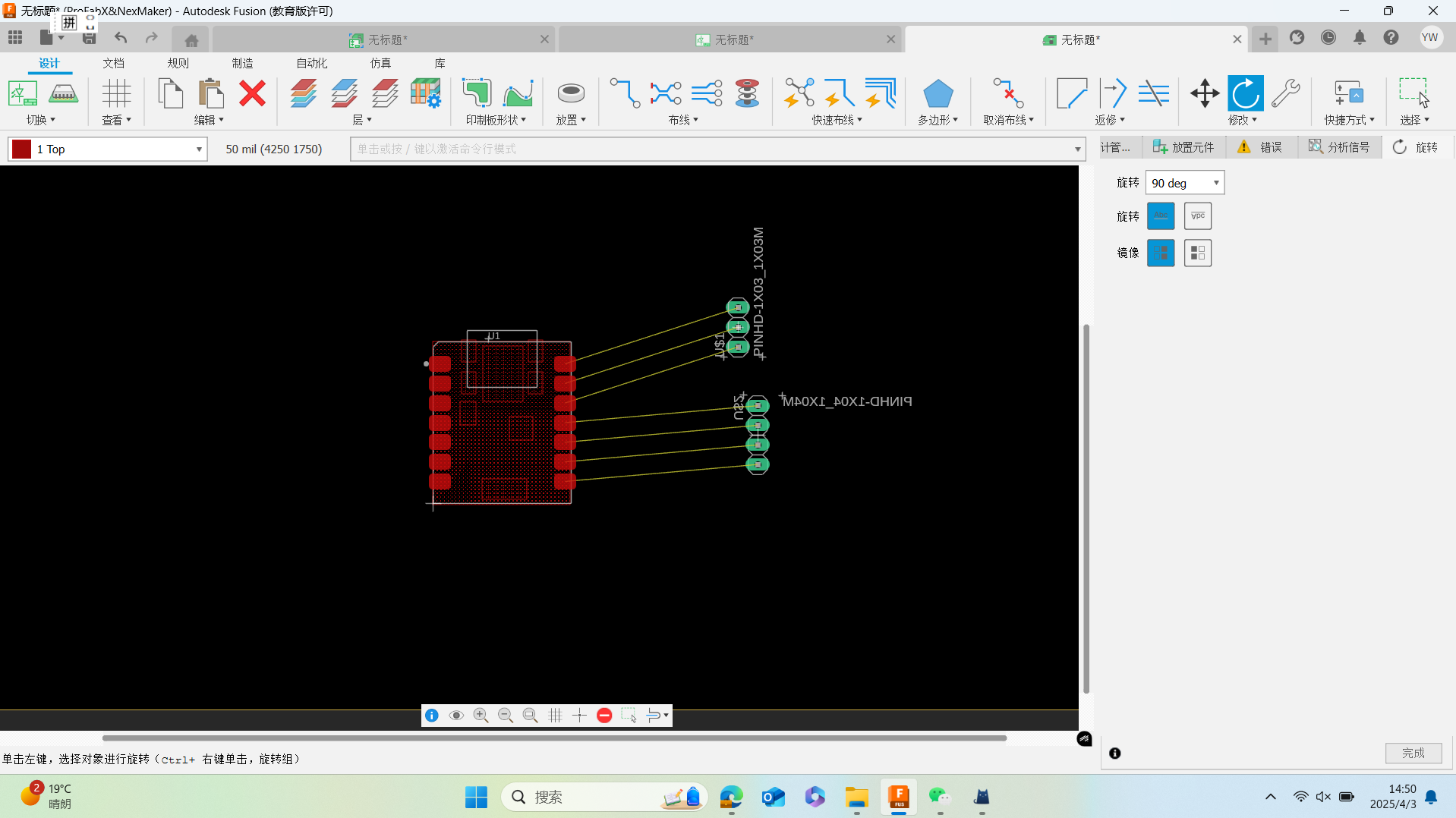
2. PCB layout design
Rearrange the compoments considering with the manufacturing process. In this step, you can adjust the wire width to fit the function.
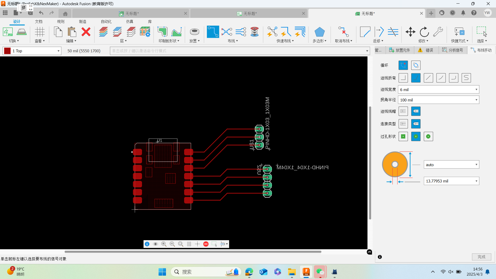
Rewrite the wire with 45 angle and connect the electric compoments.
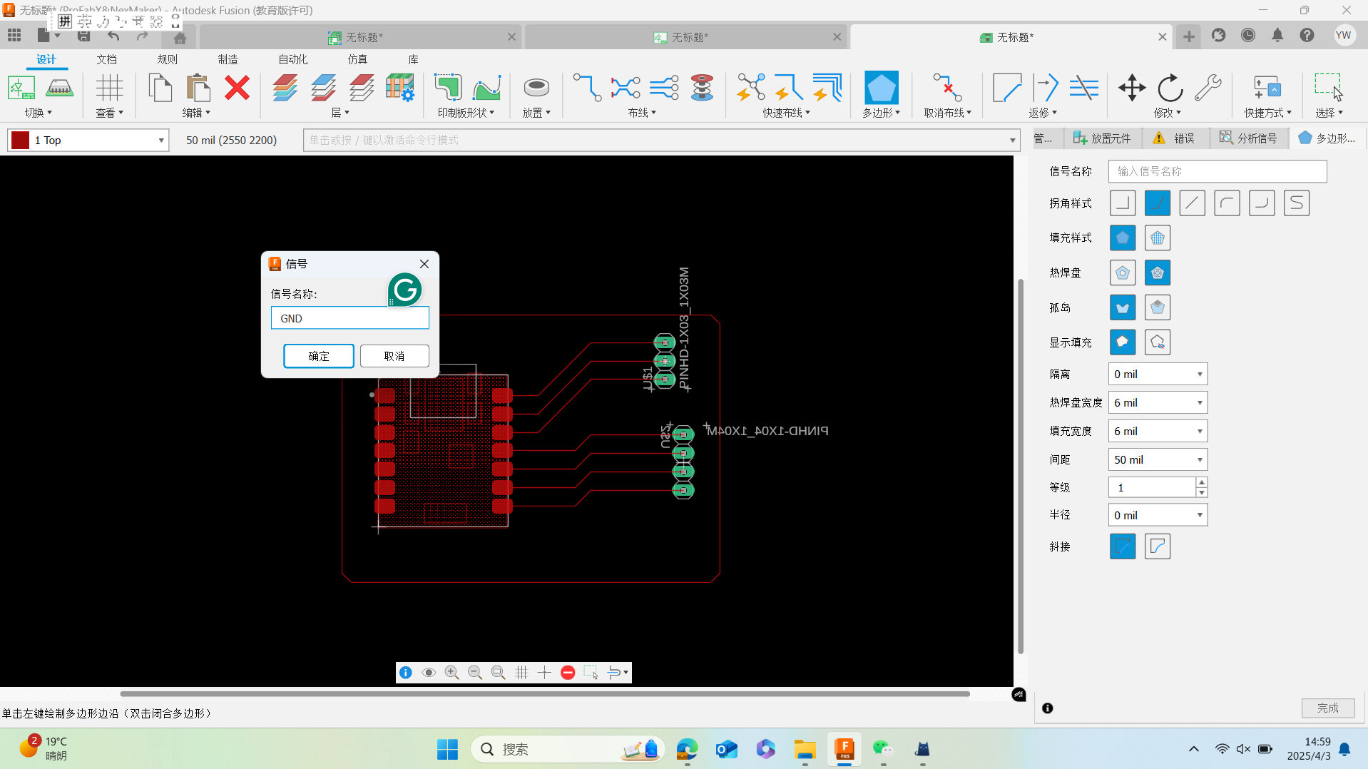
Copper laying the PCB with GND singal.
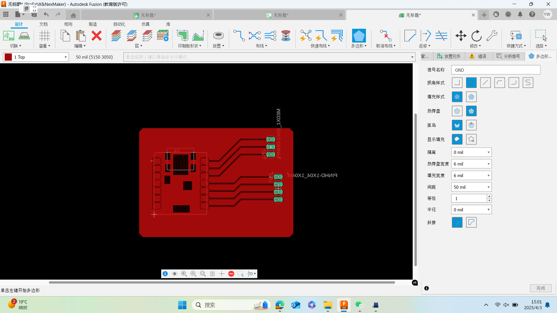
The copper laying effect is demonstrated as follows:
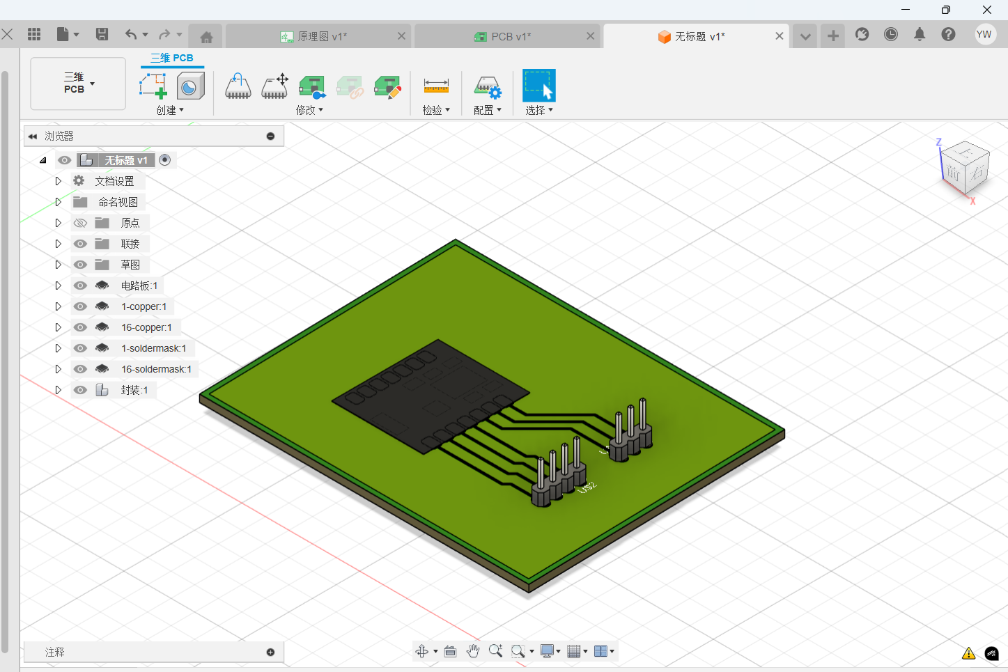
3. Convert PCB to modelling file
Finally, convert the current PCB to 3d PCB view. In this view, you can preview the PCB effect after manufacturing.
4. PCB manufacturing
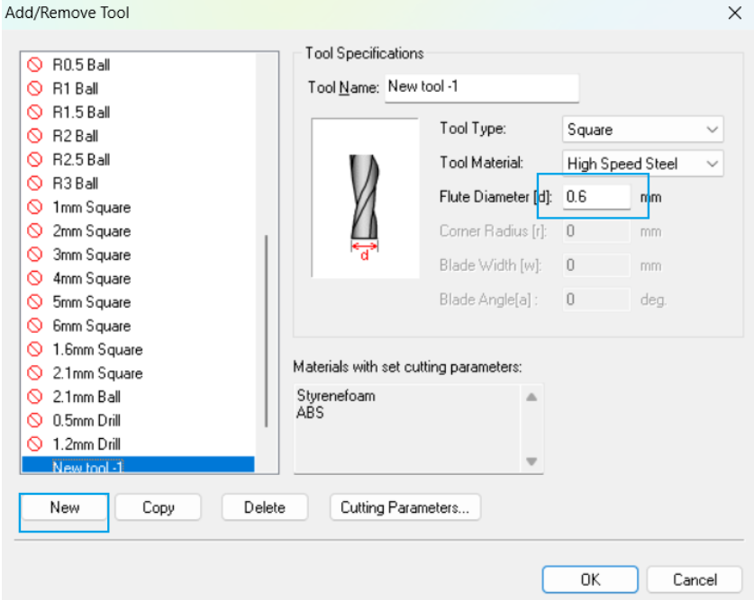
To manufacture the PCB, the Roland software was download (https://www.rolanddga.com/). Then some parameters should be set for the CNC machine.The tool diamater was set as follows.
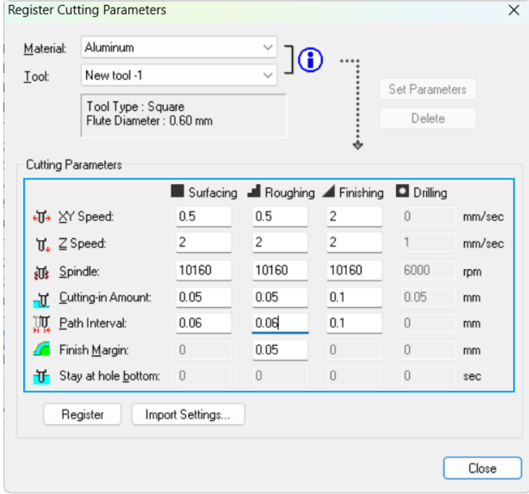
For the manufacture details, some parameters are set below,
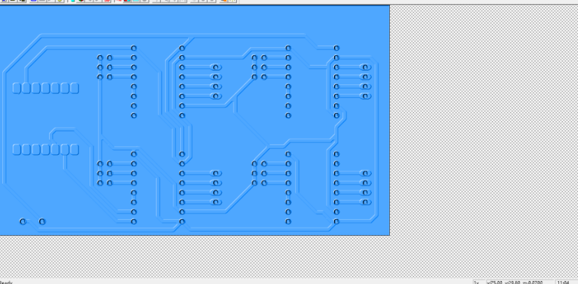
After setting the parameters, the production path is simulated by software.
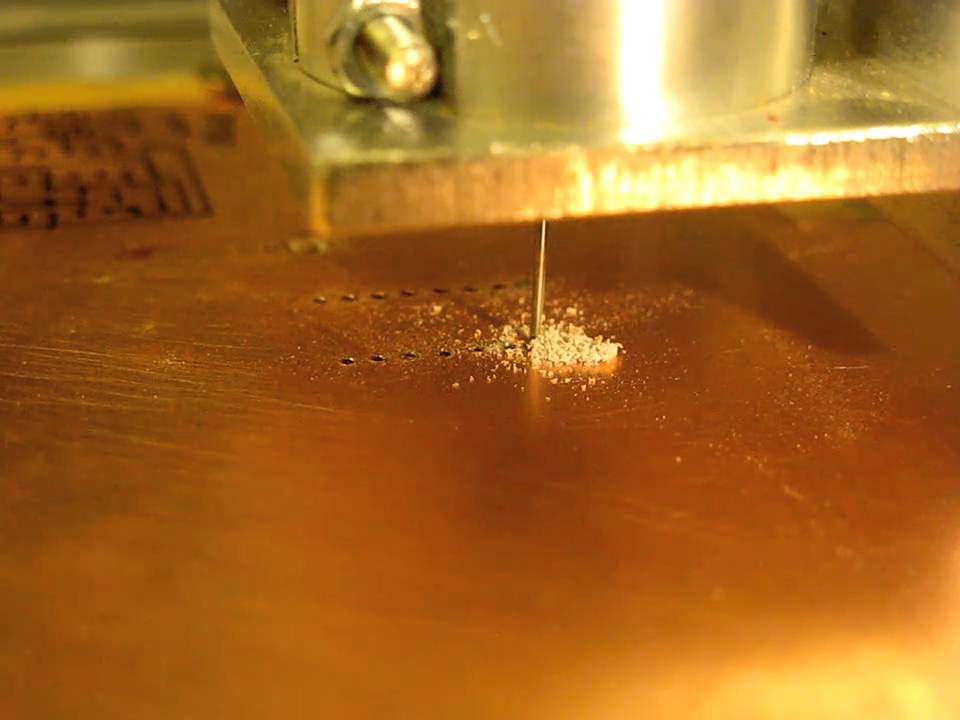
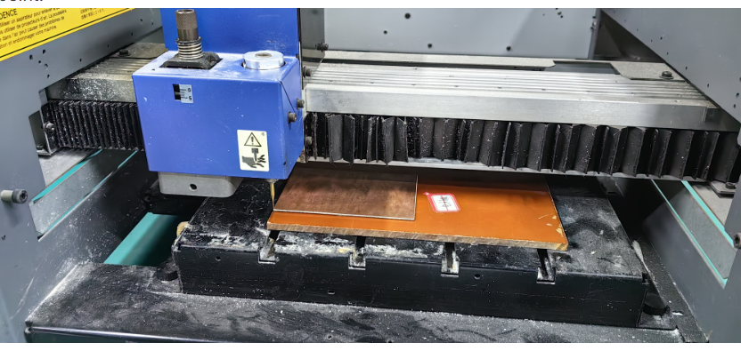
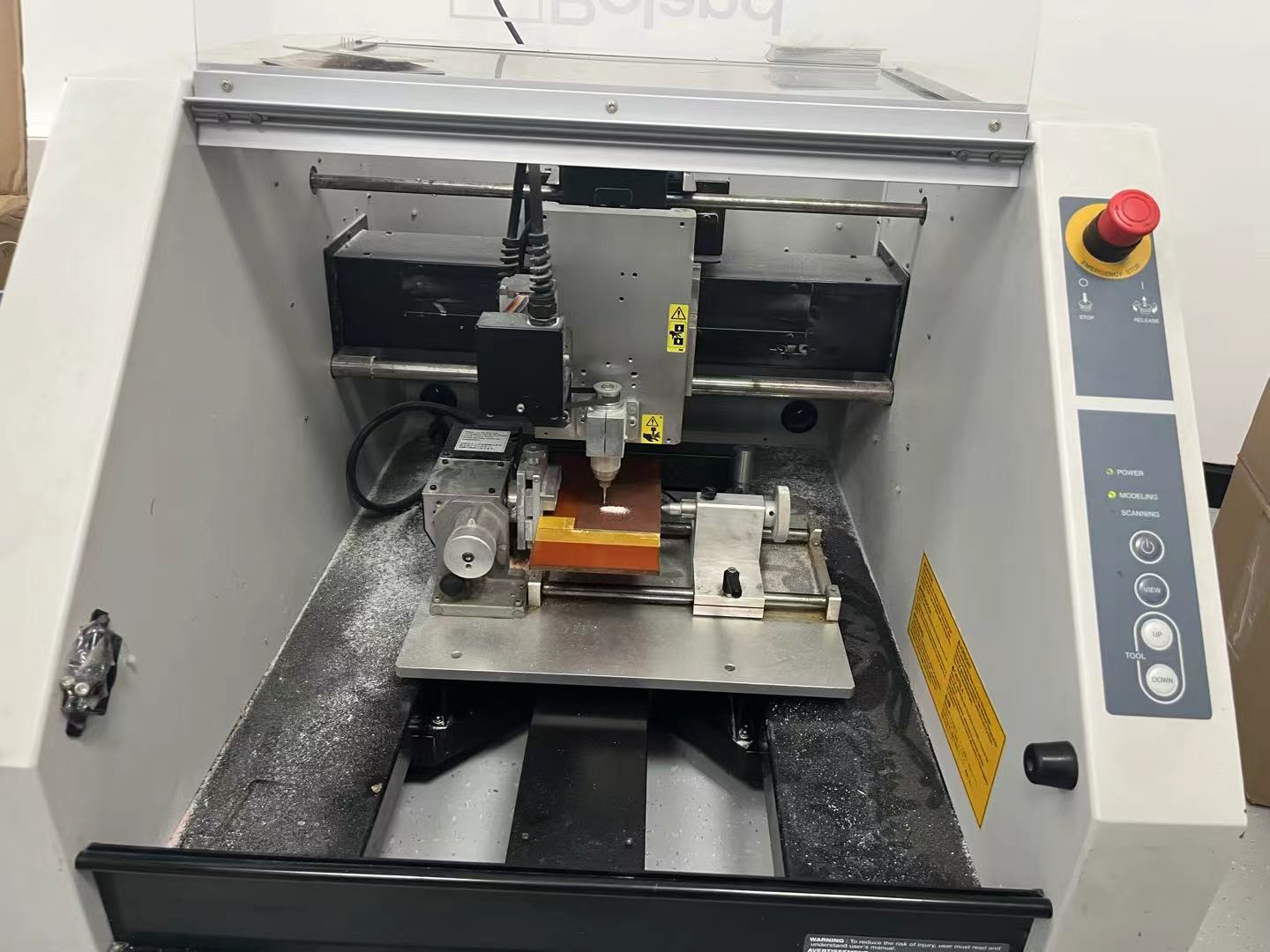
Then,Machining the PCB with CNC machine.
5. Welding the electric compoments
After manufaturing the PCB board, the electric compoments should be welding to the board.