Arduino
| Category | Name | Description | Official Link |
|---|---|---|---|
| Official | Arduino Home | Main website for hardware, software, and docs. | arduino.cc |
| Software | Arduino IDE | The official coding environment. | Download IDE |
| Software | PlatformIO | Advanced IDE extension for VS Code. | platformio.org |
| Software | Fritzing | Circuit design software for beginners. | fritzing.org |
| Software | Tinkercad | Online circuit simulation (Great for testing). | tinkercad.com |
| Hardware | Raspberry Pi | Official site for Pi computers and Pico. | raspberrypi.org |
| Hardware | Espressif | Makers of ESP32 and ESP8266 chips. | espressif.com |
| Hardware | Micro:bit | Educational coding foundation. | microbit.org |
| Hardware | SparkFun | Original creators of LilyPad. | sparkfun.com |
| Docs | Arduino Reference | Language syntax and library documentation. | Language Ref |
1. Open-Source Hardware Ecosystem Introduction
In modern electronics and intelligent systems learning, open-source hardware has become the most commonly used basic tool in maker education, IoT development, and electronic prototyping.
The term "open-source" means that circuit diagrams, schematics, and program codes are all open to the public, allowing anyone to learn, modify, and recreate.
Here are some of the most commonly used open-source hardware platforms:
Raspberry Pi
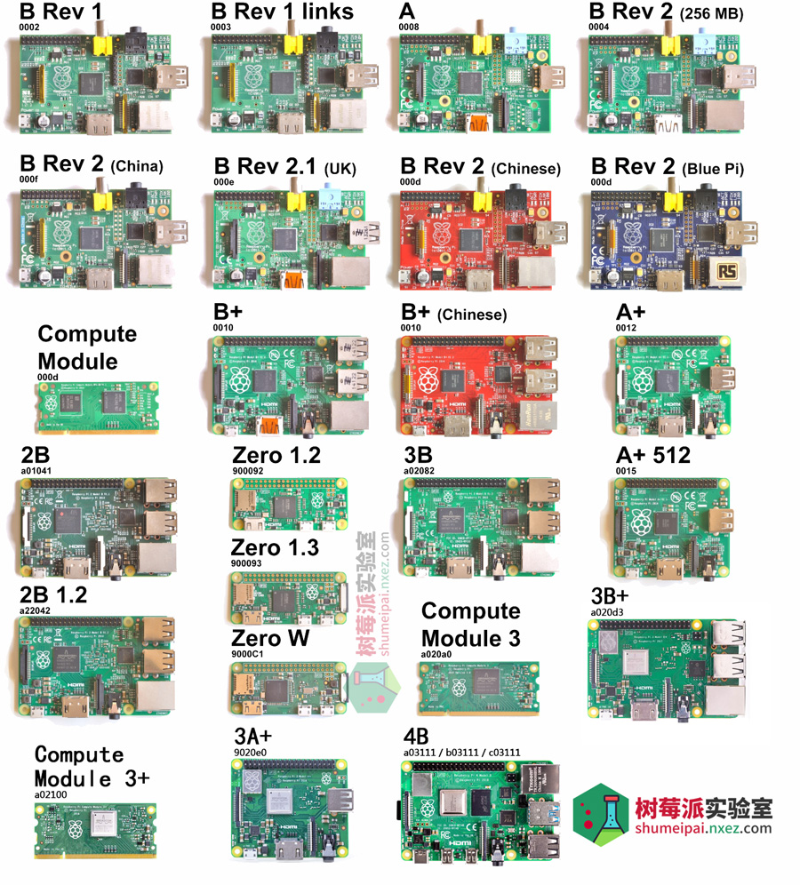 Raspberry Pi is a micro single-board computer (SBC), small enough to fit in the palm of your hand but capable of running a complete Linux system.
It supports Python, C/C++, Java, and other programming languages and can be connected to a monitor, keyboard, and mouse for use.
- Main Features:
- Equipped with an ARM processor, supports HDMI output, USB ports, and WiFi/Bluetooth communication.
- Can interface with cameras, sensors, and other modules for complex functions like image recognition and voice control.
- Common Uses:
- Smart home control center
- Small AI inference server (can run TensorFlow Lite)
- Embedded system experiments in teaching and research
Raspberry Pi is often referred to as a "programmable mini-computer" and is widely used in education and research.
LilyPad Arduino
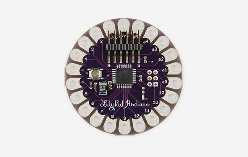 LilyPad is an Arduino board specially designed for wearable electronics projects.
Its circular shape has sewable connections, making it easy to sew into clothing.
- Main Features:
- Uses the ATmega328V chip, compatible with Arduino Uno.
- Supports battery power and can connect to modules like LEDs and sensors.
- All pins are designed with large holes for easy sewing.
- Typical Applications:
- Smart glowing clothing
- Motion capture in dance costumes
- Artistic interactive installations
LilyPad’s philosophy is “integrating electronic design into daily life,” making it ideal for artistic and design-oriented creations.
ESP32 / ESP8266 Series
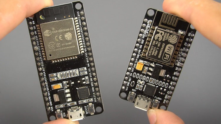 The ESP series, developed by Espressif, is a high-performance, cost-effective wireless microcontroller chip.
Compared to Arduino, it comes with built-in WiFi and Bluetooth modules, making it more suitable for connected devices.
- Main Features:
- Supports Arduino IDE, MicroPython, and other development environments.
- Dual-core CPU with a maximum frequency of 240MHz.
- Built-in wireless modules supporting HTTP, MQTT communication.
- Typical Applications:
- Smart home devices (such as smart plugs, temperature and humidity monitoring)
- IoT node data collection terminals
- Wireless sensor networks
The ESP32 has become one of the most commonly used core boards in IoT projects.
Micro:bit (BBC Educational Board)
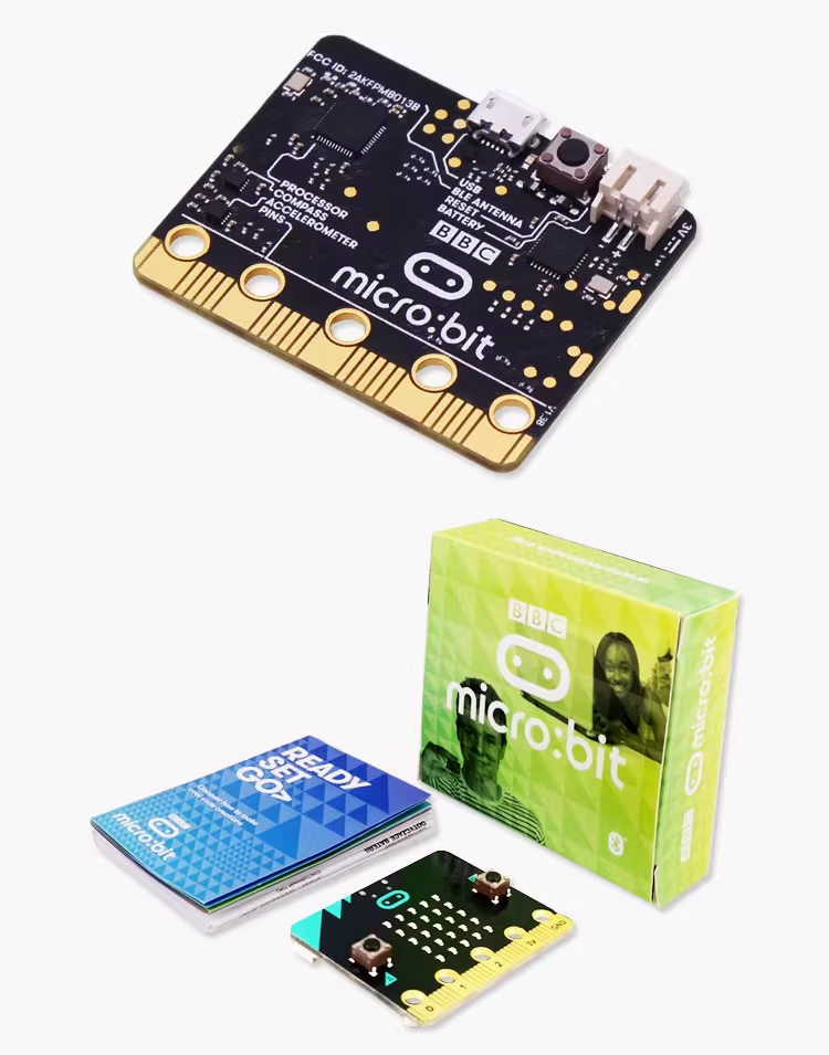 Micro:bit is an entry-level microcontroller developed by BBC for youth programming education.
It comes with multiple built-in sensors and an LED matrix, making it ideal for beginners to experience programming and interaction.
- Main Features:
- Built-in LED matrix, accelerometer, magnetometer, Bluetooth module.
- Can be programmed using graphical programming (MakeCode) or Python.
- Common Uses:
- Educational experiments, interactive games, smart car control.
Its slogan is “Let every child learn to code,” making it highly suitable for classroom teaching and beginner makers.
1.2 Hardware Comparison: ESP32 vs LilyPad Arduino
Comparison: ESP32 vs LilyPad Arduino
| Feature | ESP32 | LilyPad Arduino |
|---|---|---|
| Main Purpose | High-performance, wireless IoT development | Wearable electronics projects |
| Microcontroller | Dual-core CPU, up to 240MHz | ATmega328V chip, compatible with Arduino Uno |
| Wireless Capabilities | Built-in WiFi and Bluetooth | No built-in wireless capabilities |
| Power Source | 3.3V, USB or battery | Battery-powered (e.g., coin cell, AA) |
| Programming Language | Arduino IDE, MicroPython, ESP-IDF | Arduino IDE |
| Size | Small, compact (approx. 25mm x 50mm) | Circular design, sewable, approx. 45mm diameter |
| Pin Count | 34 GPIO pins, including analog and digital | 14 digital I/O pins |
| Typical Use Cases | IoT, smart home devices, wireless sensors | Wearable tech, smart clothing, interactive art |
Where to Buy Genuine ESP32 and LilyPad Arduino
ESP32:
Official Espressif Website: Espressif provides official sales and links to authorized distributors. You can also find documentation and SDK resources here.
- Website: https://www.espressif.com
Authorized Distributors: Check official channels like Espressif's own stores for genuine modules.
- Example: Espressif (乐鑫)
LilyPad Arduino:
Official Arduino Store: You can buy genuine LilyPad boards directly from the Arduino store.
- Website: https://store.arduino.cc
Authorized Retailers: SparkFun, Adafruit, and other trusted electronics suppliers offer authentic LilyPad products.
- Example: SparkFun LilyPad Arduino
By purchasing from these official or authorized distributors, you ensure the quality and authenticity of the hardware for your projects.
2. Learn the Arduino IDE
Arduino is an open-source hardware and software electronic prototyping platform.
It allows learners with no background in electronics to quickly get started and control sensors, motors, lights, and other devices with simple code or graphical programming.
The greatest charm of Arduino lies in its “what you see is what you get” approach:
Whether you're building a small night light, a temperature logger, or an automatic plant-watering system, just a few lines of code can make it happen.
Arduino IDE Interface Overview
Arduino IDE is the tool used to write, compile, and upload code to the Arduino board. Its interface is simple and intuitive, mainly divided into four sections:
- Menu Bar: Provides file, edit, program, tools, and help menus for file management, code editing, and board settings.
- Toolbar: Contains commonly used buttons such as compile, upload, open program, save program, and serial monitor for quick operation.
- Code Editing Area: Used to write program code, mainly consisting of
setup()andloop()sections for initialization and continuous control. - Status Bar: Displays the progress of compilation and uploading, as well as any error messages to help debug the program.
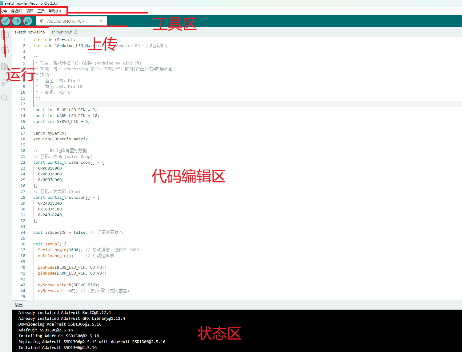
This interface is designed to help developers focus on writing code and conducting experiments without worrying about complex settings and operations.
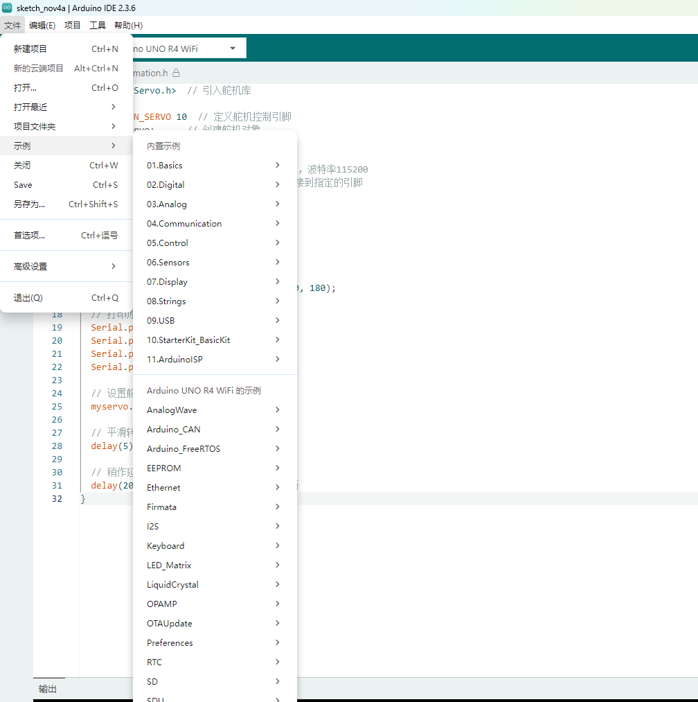
Example: The environment’s built-in example program can be opened.
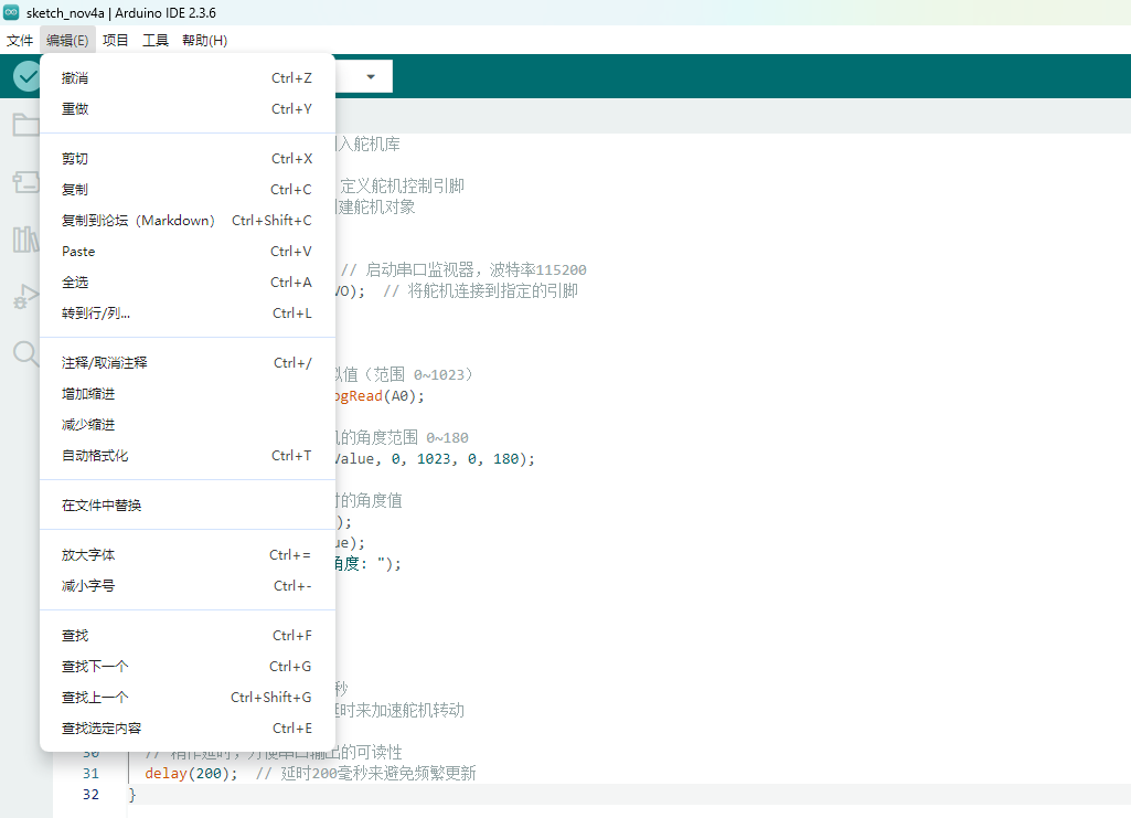
Edit: Edit the code, copy and paste, comment, indent, adjust size, find, etc. (In actual use, it is usually done with corresponding shortcut keys.)
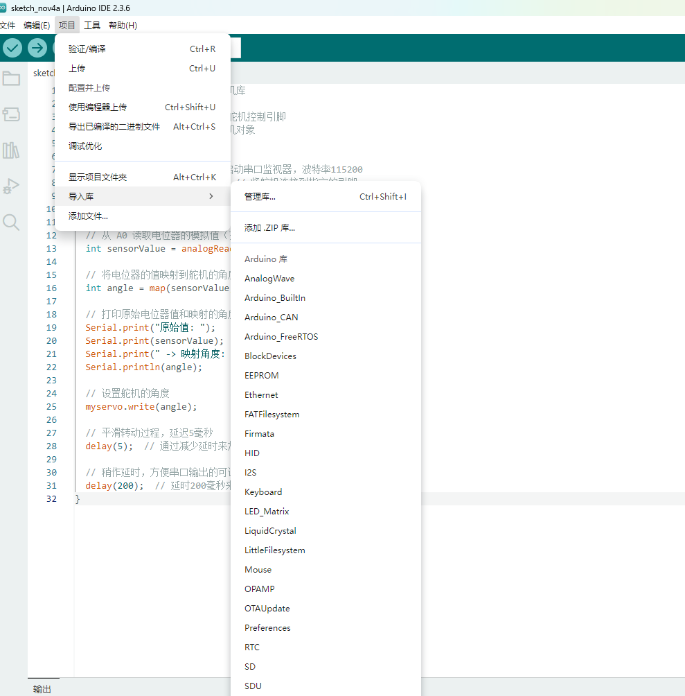
Project -> Load Library -> Library Manager: You can search for various supported libraries in the installation network, select the library to install, and click install to download and install online, which is very convenient.
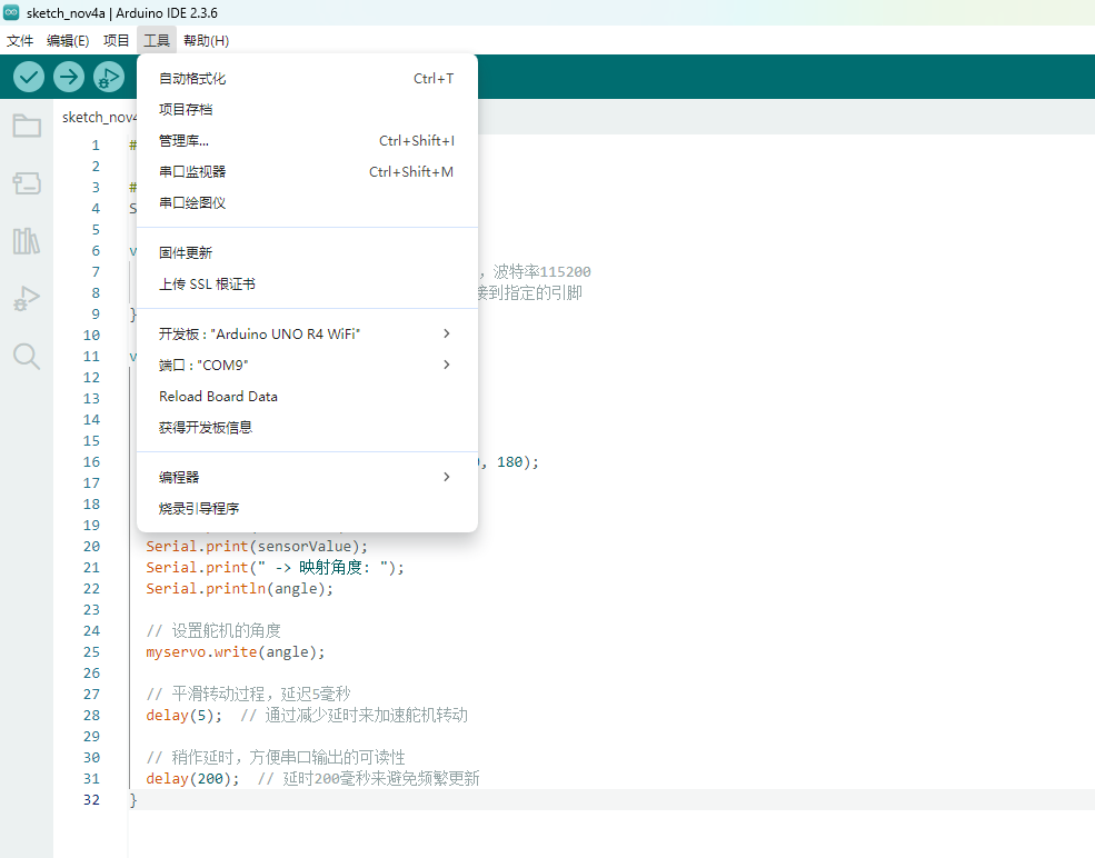
Tools -> Port: Set the port required by the Arduino IDE to download the program, which is the port through which the development board connects to the computer.
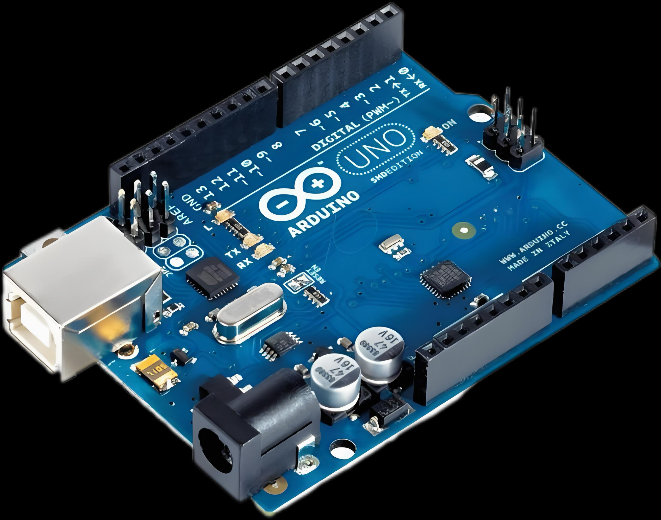
3. About Arduino Uno R4 WIFI
Arduino Uno R4 WIFI is the latest development board in the Arduino series, adding a WiFi module to make it more flexible for IoT applications.
It inherits the design philosophy of the Arduino Uno but significantly improves processing power and wireless communication.
Core Configuration
Main Chip: Renesas RA4M1 (32-bit ARM Cortex-M4)
- Flash Memory: 32KB
- SRAM: 16KB
- EEPROM: 4KB
Operating Frequency: 48 MHz
Operating Voltage: 5V
Input Voltage Range: 7V–12V (via USB or external power)
Built-in WiFi: 2.4GHz WiFi module (suitable for IoT applications)
Pin Distribution
- Digital Pins (D0–D13): Can be used for switching signal output or input.
D0 and D1 are used for serial communication. - Analog Pins (A0–A5): Can read analog signals from 0–5V, such as temperature or potentiometer values.
- PWM Output: D3, D5, D6, D9, D10, D11 support functions like dimming or servo control.
Communication and Interfaces
- USB Interface: Used for uploading programs and communicating with the computer.
- Serial Communication (UART): Can connect to Bluetooth modules, GPS, serial screens, etc.
- I2C / SPI Interfaces: Can connect to sensors, displays, and storage modules.
- Built-in WiFi: Used for IoT communication, suitable for remote data collection and control.
Other Features
- Onboard Reset Button for restarting the program.
- Supports Arduino IDE development environment, simple and intuitive.
- Expandable with various sensor modules and motor driver boards.
Arduino Input and Output
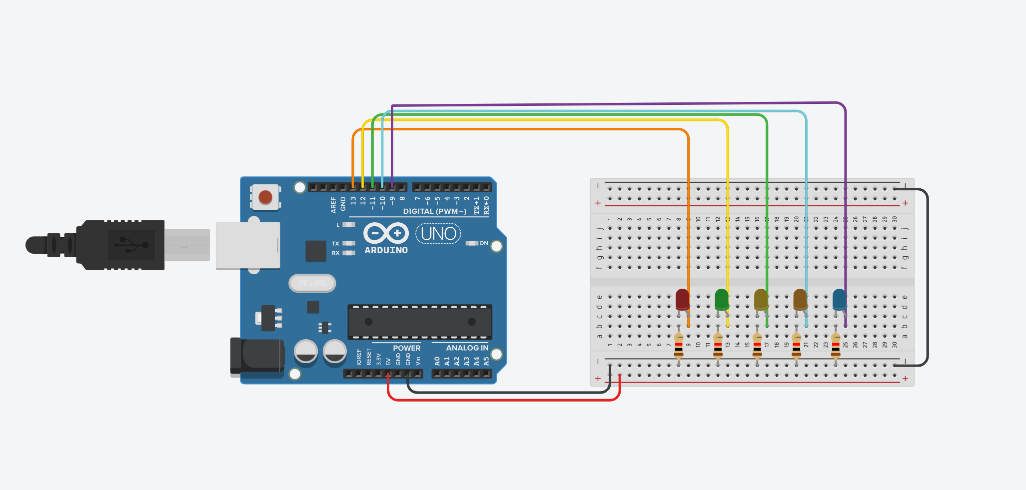
Water Flow Lamp Simulation
A water flow lamp is an effect where multiple LEDs are controlled to turn on and off in sequence, simulating the flow of water or light. This effect is commonly used in decorations and displays, especially in artistic installations or dynamic lighting effects, and can be easily implemented through programming.
Water Flow Lamp Simulation
In my project, I used Arduino Uno and 9 LEDs to implement the water flow effect. Specifically, the LEDs light up alternately from left to right and right to left, simulating the flow of water, and a flickering effect is added after each LED flows to enhance the dynamic feeling.
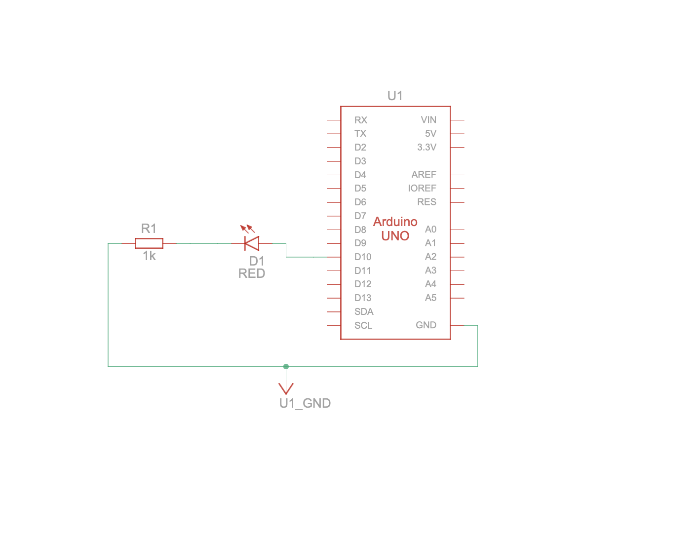
This diagram demonstrates the basic arrangement of LEDs, showing how the LEDs are laid out in a sequence. The LEDs are turned on and off one by one to simulate a flowing effect, similar to how water moves in a stream.
The diagram illustrates the control principle behind the water flow lamp. It shows how the LEDs light up sequentially from left to right and then from right to left, simulating the flowing of water. This diagram emphasizes how the sequential lighting and timing of each LED are controlled to create the water flow effect.
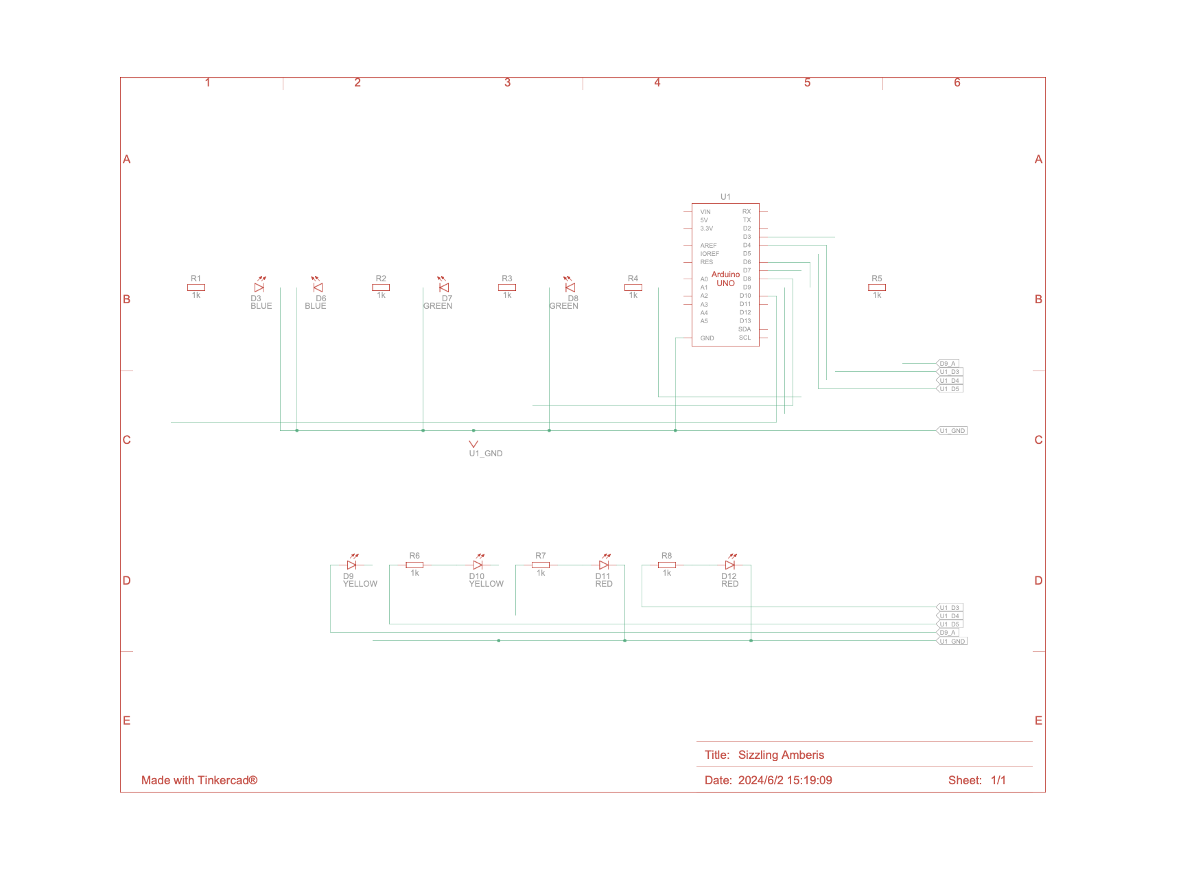
Finally, the diagram showcases the actual simulation that I created. It demonstrates how the LEDs light up in sequence from left to right, and then reverse the flow from right to left. Additionally, the last LED flickers to enhance the dynamic visual effect, mimicking the behavior of flowing water.

Code Display
Here is the complete code for the Water Flow Lamp Simulation:
int lights[] = {13, 12, 11, 10, 9};
int numLights = 5;
void setup() {
for(int i = 0; i < numLights; i++) {
pinMode(lights[i], OUTPUT);
}
}
void loop() {
int randomIndex = random(numLights);
digitalWrite(lights[randomIndex], HIGH);
delay(1000);
digitalWrite(lights[randomIndex], LOW);
delay(500);
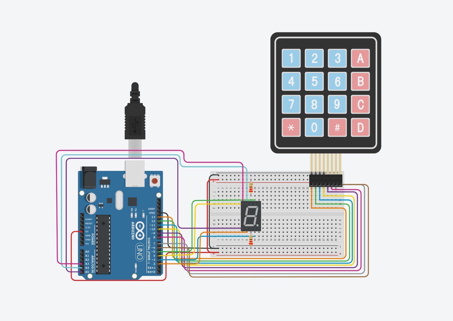
}Display control
In this project, I used Arduino Uno, 4x4 Keypad, and a 7-segment display to create a simple digital input system. The 4x4 keypad is used to input digits (0-9), and the corresponding number is displayed on the 7-segment display.
Keypad and 7-Segment Display Simulation
In my project, the 4x4 keypad allows users to press keys, and based on the key pressed, the 7-segment display will show the corresponding number. The system responds to the key inputs and displays the number dynamically, with feedback shown through the serial monitor.
This diagram demonstrates the basic arrangement of the keypad and the 7-segment display. It shows how the 4x4 keypad is connected to the Arduino and how the 7-segment display is connected to the corresponding pins.
Code Display
Here is the complete code for the Display control:
#include <Keypad.h>

const byte ROWS = 4, COLS = 4;  // Define the size of the keypad
char keys[ROWS][COLS] = {
  {'1','2','3','A'},
  {'4','5','6','B'},
  {'7','8','9','C'},
  {'*','0','#','D'}
};

byte rowPins[ROWS] = {13, 12, 11, 10};  // Row pins connected to Arduino
byte colPins[COLS] = {9, 8, 7, 6};     // Column pins connected to Arduino

Keypad keypad = Keypad(makeKeymap(keys), rowPins, colPins, ROWS, COLS);

// Define the pins for the 7-segment display (a to g)
int segPins[7] = {5, 4, 3, 2, A5, A4, A3};

// Number patterns for digits 0-9 (1 = ON)
int angka[10][7] = {
  {1,1,1,1,1,1,0}, // 0
  {0,1,1,0,0,0,0}, // 1
  {1,1,0,1,1,0,1}, // 2
  {1,1,1,1,0,0,1}, // 3
  {0,1,1,0,0,1,1}, // 4
  {1,0,1,1,0,1,1}, // 5
  {1,0,1,1,1,1,1}, // 6
  {1,1,1,0,0,0,0}, // 7
  {1,1,1,1,1,1,1}, // 8
  {1,1,1,1,0,1,1}  // 9
};

void setup() {
  // Set the segment pins as OUTPUT
  for (int i = 0; i < 7; i++) {
    pinMode(segPins[i], OUTPUT);
  }
  Serial.begin(9600);  // Initialize the serial communication
}

void loop() {
  // Get the pressed key from the keypad
  char key = keypad.getKey();

  // If a key is pressed and it is a digit (0-9), display the corresponding number
  if (key && key >= '0' && key <= '9') {
    int num = key - '0';  // Convert the character to an integer
    tampilkanAngka(num);   // Display the number on the 7-segment display
    Serial.print("Tombol: ");
    Serial.println(key);   // Print the pressed key to the serial monitor
  }
}

// Function to display the number on the 7-segment display
void tampilkanAngka(int num) {
  for (int i = 0; i < 7; i++) {
    digitalWrite(segPins[i], angka[num][i] ? LOW : HIGH);  // LOW = ON (for common cathode display)
  }
}